Introduction to Infrared Remote Control with Arduino
The Arduino IR Remote Control project is a powerful gateway into wireless communication and home automation. This comprehensive guide walks you through everything you need to know to get started with infrared communication, signal decoding, and remote-controlled LED systems using Arduino.
Understanding Infrared Communication
Infrared (IR) communication is one of the most common wireless technologies used in consumer electronics. Unlike radio frequency communication, IR uses light waves just below the visible spectrum. Remote controls use IR LEDs to transmit encoded signals that IR receivers can detect and decode.
Signal Transmission
IR remotes use 38kHz modulated signals to prevent interference from ambient light sources, ensuring reliable communication.
Receiver Technology
IR receivers like the TSOP4838 filter out the 38kHz carrier and output the original digital signal to your Arduino.
Signal Encoding
Each button press sends a unique digital code that your Arduino can decode and respond to with specific actions.
Universal Application
Works with virtually any IR remote control - TV, DVD, stereo, air conditioner, or universal remotes.
Practical Applications
The IR remote control system opens up numerous possibilities for Arduino projects:
- Home Automation: Control lights, fans, and appliances with any remote control
- Custom Controllers: Create specialized remote interfaces for your projects
- Remote Sensing: Trigger actions based on remote control signals
- Educational Tools: Learn about wireless communication and signal processing
- Accessibility Devices: Create custom control systems for specific needs
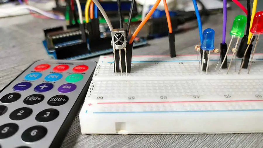
Required Components and Tools
Arduino Board
Any Arduino compatible board (Uno, Nano, Mega, etc.) with digital I/O pins
IR Receiver
TSOP4838 or similar 38kHz infrared receiver module
LEDs
3x LEDs (different colors recommended) with appropriate current-limiting resistors
Remote Control
Any standard IR remote (TV, DVD, stereo, or universal remote)
Understanding the IR Receiver
1 IR Receiver Basics
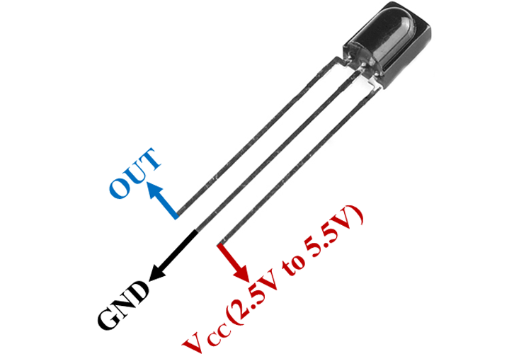
The TSOP4838 is a standard 38kHz IR receiver with three essential pins:
- Output Pin: Carries demodulated signal to Arduino (connects to digital pin)
- Ground Pin: Connects to circuit ground (GND)
- Power Pin: Connects to 5V power supply (VCC)
Step-by-Step Project Implementation
2 Phase 1: Signal Decoding
Before controlling LEDs, we need to decode the signals from your specific remote control:
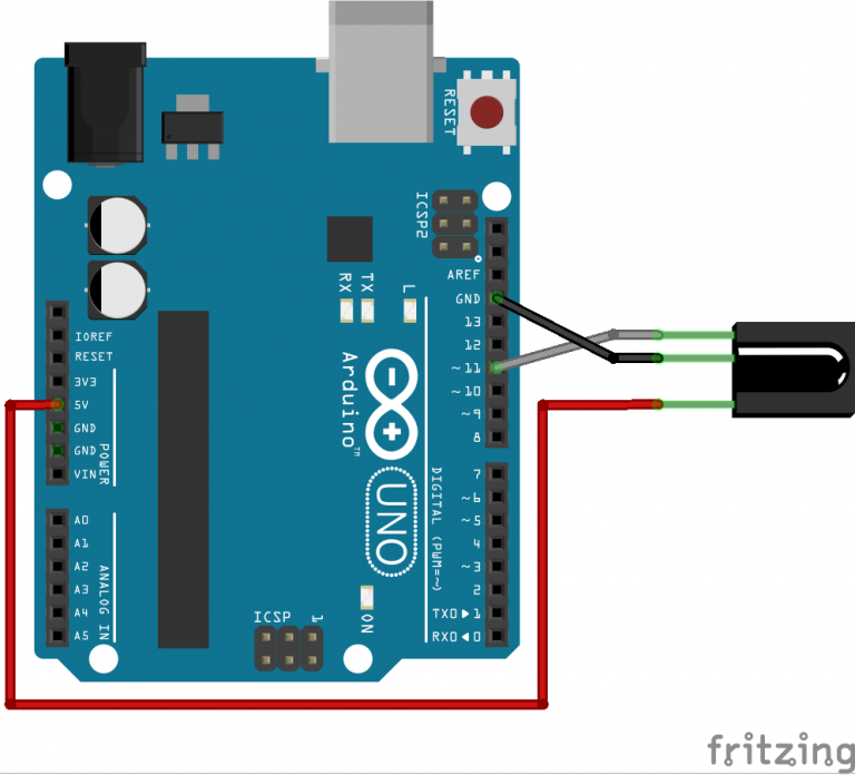
- Connect IR Receiver: Output to Pin 11, GND to GND, VCC to 5V
- Install IRremote Library: In Arduino IDE, go to Sketch > Include Library > Manage Libraries > Search for "IRremote" > Install
- Upload Decoding Code: Use the provided signal decoding program
- Test Each Button: Point remote at receiver, press buttons, record hexadecimal codes
- Map Functions: Assign 6 buttons for: LED1 ON/OFF, LED2 ON/OFF, LED3 ON/OFF
Essential Arduino Code Elements
The IRremote library by Ken Shirriff handles complex signal processing, making IR communication accessible. Here are the key code components:
| Code Element | Function | Usage Example |
|---|---|---|
| #include <IRremote.h> | Include IRremote library | Required for all IR communication functions |
| IrReceiver.begin() | Initialize IR receiver | Sets up pin and enables receiver |
| IrReceiver.decode() | Check for received signal | Returns true when IR signal detected |
| IrReceiver.decodedIRData.command | Access decoded command value | Contains hexadecimal button code |
| IrReceiver.resume() | Reset for next signal | Must be called after processing each signal |
| IrReceiver.printIRResultShort() | Print decoded data | Debugging and code identification |
Signal Decoding Code
3 Complete Signal Decoding Program
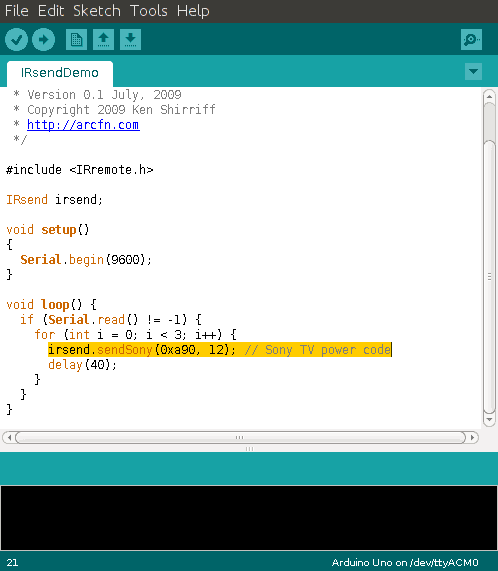
Upload this code to decode your remote's button signals:
#include <IRremote.h>

const int RECV_PIN = 11;

void setup() {
  Serial.begin(9600);
  IrReceiver.begin(RECV_PIN, ENABLE_LED_FEEDBACK); // Initialize the receiver
}

void loop() {
  if (IrReceiver.decode()) { // Check if data is received
    // Filter out unknown protocols
    if (IrReceiver.decodedIRData.protocol == UNKNOWN) {
      IrReceiver.resume(); // Resume receiving for the next signal
      return; // Skip this loop iteration
    }

    // Print only valid data
    IrReceiver.printIRResultShort(&Serial); // Print complete received data in one line

    IrReceiver.resume(); // Resume receiving for the next signal
  }
  delay(100);
}
How It Works: This code initializes the IR receiver on pin 11 and continuously checks for incoming signals. When you press a remote button, it prints the decoded information to the Serial Monitor. Record the hexadecimal "command" value for each of your 6 chosen buttons.
Complete LED Control System
4 Phase 2: LED Control Circuit
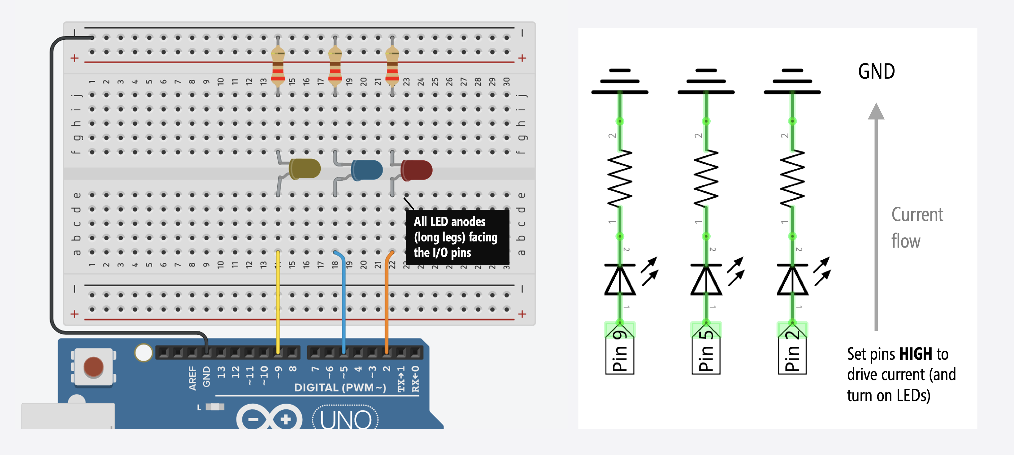
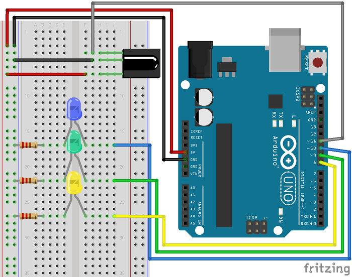
After decoding your remote signals, build the complete LED control circuit:
- LED Connections: Blue LED to Pin 10, Green LED to Pin 9, Yellow LED to Pin 8
- Resistors: 220Ω-330Ω current-limiting resistors for each LED
- Power: Connect all grounds together, power via USB or external supply
- IR Receiver: Keep connected to Pin 11 as in decoding phase
Complete LED Control Code
5 Final Control Program
Insert your recorded button codes into this complete control program:
/*
 * Based on IRremote Library - Ken Shirriff
*/

#include <IRremote.h>

const int RECV_PIN = 11;

const int bluePin = 10;
const int greenPin = 9;
const int yellowPin = 8;

void setup() {
  Serial.begin(9600); // Start serial communication
  IrReceiver.begin(RECV_PIN, ENABLE_LED_FEEDBACK); // Start the receiver

  pinMode(bluePin, OUTPUT);    // Set the pins as output
  pinMode(greenPin, OUTPUT);
  pinMode(yellowPin, OUTPUT);
}

void loop() {
  // Decode the infrared input
  if (IrReceiver.decode()) {
    if (IrReceiver.decodedIRData.protocol == UNKNOWN) {
      IrReceiver.resume(); // Resume receiving for the next signal
      return; // Skip this loop iteration
    }

    // Print the received command for debugging
    IrReceiver.printIRResultShort(&Serial);

    switch (IrReceiver.decodedIRData.command) {
      case 0x01: // REPLACE with your LED1 ON code
        digitalWrite(bluePin, HIGH);
        Serial.println("Blue LED ON");
        break;

      case 0x02: // REPLACE with your LED2 ON code
        digitalWrite(greenPin, HIGH);
        Serial.println("Green LED ON");
        break;

      case 0x03: // REPLACE with your LED3 ON code
        digitalWrite(yellowPin, HIGH);
        Serial.println("Yellow LED ON");
        break;

      case 0x04: // REPLACE with your LED1 OFF code
        digitalWrite(bluePin, LOW);
        Serial.println("Blue LED OFF");
        break;

      case 0x05: // REPLACE with your LED2 OFF code
        digitalWrite(greenPin, LOW);
        Serial.println("Green LED OFF");
        break;

      case 0x06: // REPLACE with your LED3 OFF code
        digitalWrite(yellowPin, LOW);
        Serial.println("Yellow LED OFF");
        break;

      default: // Unknown command
        Serial.println("Unknown Command");
        break;
    }

    IrReceiver.resume(); // Receive the next value
  }
  delay(10);
}
Code Explanation: This program uses a switch-case structure to map specific button codes to LED control actions. When you press a programmed button, the corresponding LED toggles on or off, and the action is confirmed in the Serial Monitor.
Testing and Verification
6 System Testing Procedure
After uploading your code with your specific button codes:
- Power Up: Connect Arduino to power source
- Open Serial Monitor: Set to 9600 baud rate
- Test Each Button: Press programmed buttons one by one
- Verify Responses: Check both LED actions and serial monitor feedback
- Troubleshoot: If issues occur, review wiring and code values
Advanced Applications
7 Expanding Your Project
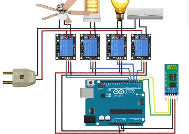
Once you've mastered basic LED control, expand your project with these ideas:
- Relay Control: Replace LEDs with relays to control household appliances
- Motor Control: Control motor speed and direction with remote buttons
- Multiple Functions: Program additional buttons for "All ON," "All OFF," or dimming functions
- Sensor Integration: Combine with sensors for environment-responsive systems
- Home Automation: Create a complete remote-controlled home system
Power Management Considerations
8 Optimizing Power Usage
For battery-powered or energy-efficient applications:
- Current Limiting: Ensure proper resistor values to minimize LED power consumption
- Sleep Modes: Implement Arduino sleep modes when not actively receiving commands
- Efficient Code: Use non-blocking code patterns and minimize delay() usage
- Power Supply: Choose appropriate power source based on total current requirements
// Example power-saving modification
// Instead of delay(10) in main loop:
unsigned long previousMillis = 0;
const long interval = 10;

void loop() {
  unsigned long currentMillis = millis();

  if (currentMillis - previousMillis >= interval) {
    previousMillis = currentMillis;

    // Your IR decoding and control code here
    if (IrReceiver.decode()) {
      // Process IR signal
      IrReceiver.resume();
    }
  }

  // Other tasks can run here without blocking
}
This non-blocking approach allows other tasks to run while maintaining regular IR checks, improving system responsiveness and enabling power-saving features.
Troubleshooting Common Issues
No Serial Monitor Output
Solution: Check IR receiver connections, verify remote has batteries, ensure correct baud rate (9600), test with different remote.
LEDs Not Lighting
Solution: Verify LED polarity (long leg = anode), check resistor values, test LEDs directly with 5V, confirm pinMode set to OUTPUT.
Intermittent Signal Reception
Solution: Ensure direct line-of-sight, check for IR interference sources, verify adequate power supply, reposition receiver.
Wrong LED Responds
Solution: Double-check button code assignments, re-decode remote signals, verify case statement values match decoded commands.
Next Steps and Project Expansion
With the foundation established in this guide, consider these advanced project directions:
- Universal Remote: Program your Arduino to learn and emulate multiple remotes
- IR Transmitter: Add IR LED to send signals and control other devices
- Home Automation Hub: Create central controller for multiple IR devices
- Gesture Control: Implement gesture recognition using IR sensor arrays
- Robotics Control: Use remote to control robot movements and functions