Introduction to Arduino Membrane Keypads
Membrane keypads provide an affordable and effective solution for adding user input capabilities to your Arduino projects. These thin, flexible input devices allow you to create interactive interfaces for countless microcontroller applications, from security systems to data entry terminals and custom controllers.
Understanding Membrane Keypads
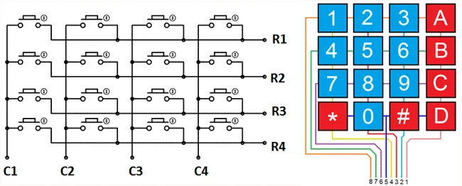
Membrane keypads are matrix-based input devices consisting of multiple layers with printed circuits. When you press a button, the top conductive layer makes contact with the bottom layer, completing a circuit at a specific row-column intersection.
Affordable
Typically cost less than $2, making them accessible for all budget levels and perfect for prototyping.
Matrix Design
Uses row/column matrix to minimize pin usage - N×M keypad needs only N+M pins instead of N×M.
Variety Available
Available in multiple sizes (3×4, 4×4) with numeric, alphanumeric, or custom button labels.
Universal Compatibility
Works with any microcontroller, not just Arduino - perfect for ESP32, Raspberry Pi, and other platforms.
How Membrane Keypads Work
The matrix design is the key to understanding how membrane keypads operate efficiently with minimal pin usage:
| Keypad Size | Buttons | Rows | Columns | Pins Required |
|---|---|---|---|---|
| 3×4 | 12 buttons | 4 rows | 3 columns | 7 pins (4+3) |
| 4×4 | 16 buttons | 4 rows | 4 columns | 8 pins (4+4) |
Matrix Addressing: Each button is assigned to a specific row and column intersection. For example, in a 3×4 keypad:
- Button "1" = Row 1, Column 1 (R1C1)
- Button "2" = Row 1, Column 2 (R1C2)
- Button "9" = Row 3, Column 3 (R3C3)
- "*" Button = Row 4, Column 1 (R4C1)
- "#" Button = Row 4, Column 3 (R4C3)
Required Components
Arduino Board
Arduino Uno, Nano, Mega, or any compatible microcontroller board
Membrane Keypad
3×4 or 4×4 membrane keypad (available online for under $2)
Jumper Wires
Male-to-male jumper wires for connecting keypad to Arduino
USB Cable
For programming Arduino and powering during development
Step-by-Step Wiring Guide
1 Standard 3×4 Keypad Wiring
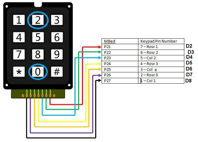
For a typical 3×4 membrane keypad, connect the pins as follows:
| Keypad Pin | Arduino Pin | Function |
|---|---|---|
| Row 1 | Digital Pin 8 | First row connection |
| Row 2 | Digital Pin 7 | Second row connection |
| Row 3 | Digital Pin 6 | Third row connection |
| Row 4 | Digital Pin 5 | Fourth row connection |
| Column 1 | Digital Pin 4 | First column connection |
| Column 2 | Digital Pin 3 | Second column connection |
| Column 3 | Digital Pin 2 | Third column connection |
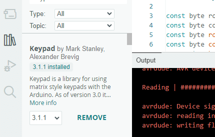
Installing the Keypad Library
2 Library Installation Process
The Arduino Keypad Library simplifies programming by handling the complex matrix scanning for you. Follow these steps:
- Download the Library: Get the Keypad library from the official Arduino library manager or GitHub repository
- Install via Arduino IDE:
- Open Arduino IDE
- Go to Sketch → Include Library → Manage Libraries
- Search for "Keypad" and install the library by Mark Stanley and Alexander Brevig
- Manual Installation Alternative:
- Download the ZIP file from GitHub
- In Arduino IDE: Sketch → Include Library → Add .ZIP Library
- Select the downloaded file
- Restart Arduino IDE to ensure the library loads properly
Basic Keypad Code Example
3 Complete Working Code
Here's the complete code to get your keypad working with Arduino and displaying pressed keys in the Serial Monitor:
#include// Define keypad size const byte ROWS = 4; // Four rows const byte COLS = 3; // Three columns // Define keypad character matrix char keys[ROWS][COLS] = { {'1', '2', '3'}, {'4', '5', '6'}, {'7', '8', '9'}, {'#', '0', '*'} }; // Connect keypad row pins to these Arduino pins byte rowPins[ROWS] = {8, 7, 6, 5}; // Connect keypad column pins to these Arduino pins byte colPins[COLS] = {4, 3, 2}; // Create Keypad object Keypad keypad = Keypad(makeKeymap(keys), rowPins, colPins, ROWS, COLS); void setup() { Serial.begin(9600); // Initialize serial communication Serial.println("Keypad initialized. Press keys to see output."); } void loop() { char key = keypad.getKey(); // Check for key press if (key != NO_KEY) { // If a key was pressed Serial.print("Key pressed: "); Serial.println(key); } }
Code Explanation
Library Inclusion
#include <Keypad.h> gives access to Keypad library functions that handle matrix scanning and debouncing.
Layout Definition
ROWS and COLS constants define your keypad's physical dimensions (4 rows, 3 columns).
Key Mapping
The keys array defines what character each physical button represents in the matrix.
Pin Configuration
rowPins and colPins arrays specify which Arduino pins connect to which keypad rows and columns.
Adapting Code for Different Keypads
4 Customizing for 4×4 Keypads
If you have a 4×4 keypad instead of 3×4, modify the code as follows:
#include// Change columns from 3 to 4 const byte ROWS = 4; // Four rows const byte COLS = 4; // Four columns (changed from 3) // Update key matrix for 16 buttons char keys[ROWS][COLS] = { {'1', '2', '3', 'A'}, {'4', '5', '6', 'B'}, {'7', '8', '9', 'C'}, {'*', '0', '#', 'D'} }; // Adjust pin arrays - add fourth column pin byte rowPins[ROWS] = {9, 8, 7, 6}; // Example pins byte colPins[COLS] = {5, 4, 3, 2}; // Added fourth column pin Keypad keypad = Keypad(makeKeymap(keys), rowPins, colPins, ROWS, COLS); void setup() { Serial.begin(9600); } void loop() { char key = keypad.getKey(); if (key != NO_KEY) { Serial.println(key); } }
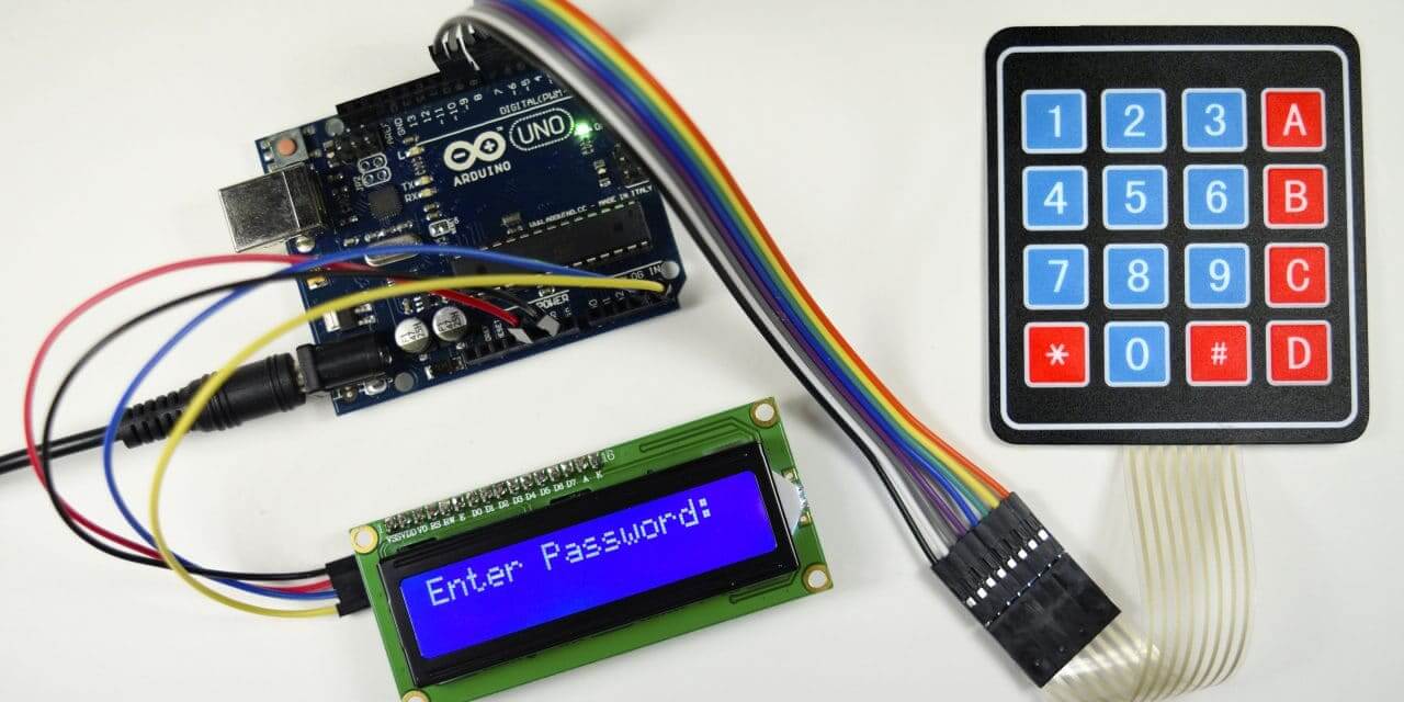
Password Verification System
5 Advanced Project: Secure Access

Create a password-protected system that grants access only when the correct code is entered:
#includeconst byte ROWS = 4; const byte COLS = 3; char keys[ROWS][COLS] = { {'1', '2', '3'}, {'4', '5', '6'}, {'7', '8', '9'}, {'#', '0', '*'} }; byte rowPins[ROWS] = {8, 7, 6, 5}; byte colPins[COLS] = {4, 3, 2}; Keypad keypad = Keypad(makeKeymap(keys), rowPins, colPins, ROWS, COLS); const String password = "1234"; // Set your password here String inputPassword; void setup() { Serial.begin(9600); inputPassword.reserve(32); // Reserve memory for input Serial.println("Enter password (4 digits) followed by #"); } void loop() { char key = keypad.getKey(); if (key) { if (key == '#') { // Check password when # is pressed if (inputPassword == password) { Serial.println("Access granted!"); // Add your access granted code here (LED, servo, etc.) } else { Serial.println("Access denied!"); } inputPassword = ""; // Clear input } else if (key == '*') { // Clear input with * inputPassword = ""; Serial.println("Input cleared."); } else { // Append digit to input inputPassword += key; Serial.print("*"); // Show asterisk for each digit } } }
Keypad with LCD Display
6 Complete User Interface
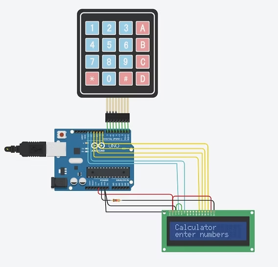
Combine your keypad with an LCD for a complete user interface system:
#include#include // Keypad setup const byte ROWS = 4; const byte COLS = 3; char keys[ROWS][COLS] = { {'1', '2', '3'}, {'4', '5', '6'}, {'7', '8', '9'}, {'#', '0', '*'} }; byte rowPins[ROWS] = {8, 7, 6, 5}; byte colPins[COLS] = {4, 3, 2}; Keypad keypad = Keypad(makeKeymap(keys), rowPins, colPins, ROWS, COLS); // LCD setup (adjust pins to match your connections) LiquidCrystal lcd(12, 11, 10, 9, 8, 7); String inputString = ""; void setup() { lcd.begin(16, 2); // 16 columns, 2 rows lcd.print("Enter value:"); } void loop() { char key = keypad.getKey(); if (key) { lcd.setCursor(0, 1); // Move to second row if (key >= '0' && key <= '9') { // Handle numeric input inputString += key; lcd.print(key); } else if (key == '#') { // Process entered value if (inputString.length() > 0) { lcd.clear(); lcd.print("Entered: "); lcd.print(inputString); delay(2000); lcd.clear(); lcd.print("Enter value:"); inputString = ""; } } else if (key == '*') { // Clear input inputString = ""; lcd.clear(); lcd.print("Enter value:"); } } }
Using I2C Port Expanders
7 Saving Digital Pins
Since membrane keypads consume 7-8 I/O pins, you might run out of pins in complex projects. The solution is using an I2C port expander like the PCF8574:
Reduced Pin Usage
Control 8+ devices with just 2 Arduino pins (SDA and SCL) instead of individual connections.
Daisy-Chaining
Connect multiple I2C devices on the same bus - keypad, LCD, sensors all on two wires.
Finding Modules
Search for "I2C 8574 I/O expander" online to find affordable modules (under $5).
Library Support
Use modified Keypad libraries that support I2C communication with port expanders.
Troubleshooting Common Issues
Keys Not Registering
Solution: Check all wiring connections, verify pin assignments match your wiring, use a multimeter to test keypad button continuity.
Multiple Keys Registering
Solution: Add pull-up resistors (10kΩ) on column pins, ensure you're using the latest Keypad library, add small delay in loop.
Unresponsive in Complex Projects
Solution: Implement interrupt service routines for key detection, increase scanning priority, simplify main loop.
Need More Digital Pins
Solution: Use I2C port expander as described above, or consider multiplexing techniques for large projects.
Creative Project Ideas
Digital Combination Lock
Create a secure lock system that activates a solenoid or servo when correct code is entered. Add LED indicators for feedback.
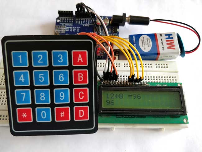
Arduino Calculator
Build a simple arithmetic calculator that displays results on LCD screen. Start with basic operations and expand functionality.
Menu Navigation System
Use keypad to navigate through complex menus on LCD display. Implement scrolling, selection, and return functionality.
Home Automation Interface
Control lights, appliances, or other devices by entering codes on keypad. Add relay modules for higher-voltage control.
Optimization Techniques
8 Advanced Programming Tips
For more advanced projects, implement these optimization techniques:
Debouncing Enhancement
char key = keypad.getKey();
if (key != NO_KEY) {
  delay(50); // Additional debounce delay
  char key2 = keypad.getKey();
  if (key == key2) {
    // Key press confirmed
    Serial.println(key);
  }
}
Non-blocking Code Implementation
unsigned long lastKeyTime = 0;
const unsigned long keyTimeout = 1000; // 1 second

void loop() {
  char key = keypad.getKey();

  if (key != NO_KEY) {
    lastKeyTime = millis();
    // Process key press
  }

  // Other non-blocking code here
  if (millis() - lastKeyTime > keyTimeout) {
    // Timeout action after no key press
  }
}
Conclusion and Next Steps
Membrane keypads offer an incredibly affordable and versatile way to add user input to your Arduino projects. With the knowledge from this tutorial, you can now:
- Connect any membrane keypad to your Arduino with proper wiring
- Program it to detect and respond to key presses using the Keypad library
- Troubleshoot common connection and coding issues
- Expand your projects with LCD displays and other components
- Optimize for complex applications and power efficiency
The versatility of membrane keypads makes them suitable for countless applications, from simple input devices to complex control systems. Remember to share your creations with the Arduino community, and don't hesitate to consult datasheets and online forums if you encounter keypads with non-standard pinouts.