Introduction to Relay Modules
Relay modules are essential components in electronics projects that allow you to control high-voltage circuits with low-voltage microcontroller signals. If you're looking to automate home appliances, create IoT devices, or build industrial control systems, understanding how to interface relay modules with Arduino opens up endless possibilities.
What is a Relay and How Does It Work?
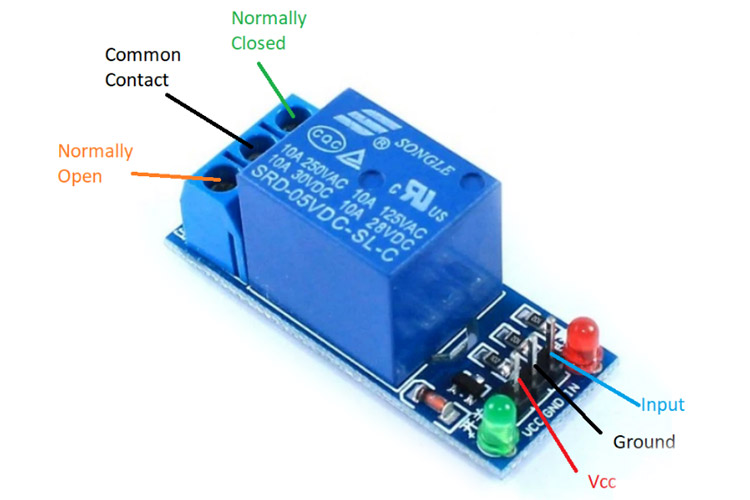
At its core, a relay is an electrically operated switch. It uses an electromagnet to mechanically control one or more switch contacts. When a small current flows through the relay's coil, it creates a magnetic field that pulls the internal switch contacts together or apart, depending on the relay type.
Electromagnet Coil
The low-voltage control side that creates magnetic field when energized
Common Terminal (COM)
The central contact that connects to either NO or NC contacts
Normally Open (NO)
Contact that closes when relay is activated, completing the circuit
Normally Closed (NC)
Contact that opens when relay is activated, breaking the circuit
Why Use Relay Modules?
Relay modules provide critical advantages over direct connections:
- Voltage Isolation: Keep your Arduino safe from high-voltage spikes and electrical noise
- Current Capacity: Handle much higher currents than microcontroller pins (typically 10-30A)
- Safety: Physical separation between low-voltage control and high-voltage load circuits
- Versatility: Control both AC and DC devices regardless of Arduino's DC-only capability
- Reliability: Dedicated driver circuits with protection diodes and status LEDs
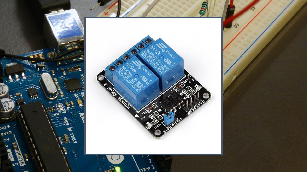
Types of Relay Modules for Arduino
Single Channel
Perfect for simple on/off control of a single device. Includes protection diodes and screw terminals.
Dual Channel
Allow independent control of two separate circuits. Ideal for coordinated device control.
4/8-Channel Modules
Expand control capabilities for complex automation systems. Often use I2C/SPI to save pins.
Solid State Relays
Use semiconductors instead of mechanical contacts. Silent, fast switching, longer lifespan.
Essential Components for This Tutorial
1 Required Components
To follow along with the practical examples, gather these components:
- Arduino Board: Uno, Nano, Mega, or similar microcontroller
- Relay Module: Single or multi-channel based on your project needs
- Jumper Wires: Male-to-female and male-to-male for connections
- Breadboard: For prototyping and testing circuits
- Test Load: LED with 220Ω resistor or small DC motor for testing
- Power Supply: For high-power loads (separate from Arduino power)
- Multimeter: For testing continuity and voltage levels
Relay Module Specifications Explained
| Specification | Typical Values | Importance |
|---|---|---|
| Control Voltage | 5V or 3.3V | Must match Arduino output voltage |
| Load Voltage (AC) | Up to 250V AC | Maximum AC voltage relay can switch |
| Load Voltage (DC) | Up to 30V DC | Maximum DC voltage relay can switch |
| Load Current | 10A (standard modules) | Maximum current through contacts |
| Trigger Type | Low-level or High-level | Determines activation logic (LOW or HIGH signal) |
| Contact Configuration | SPDT or DPDT | Single/Double Pole Double Throw switching options |
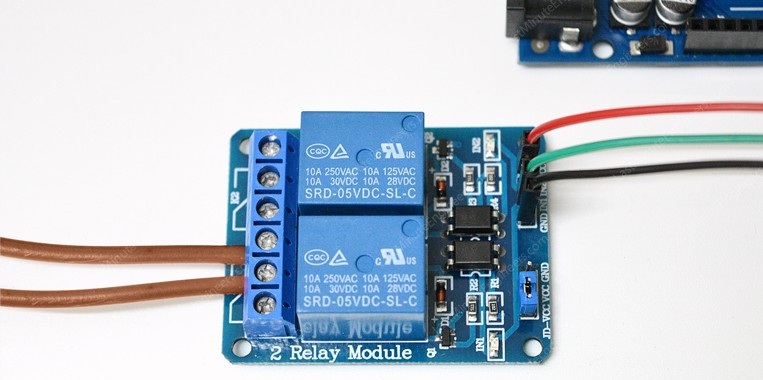
Step-by-Step Wiring Instructions
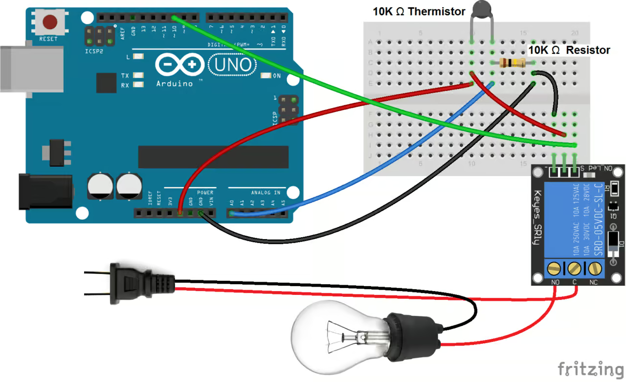
2 Basic Single Relay Module Connection
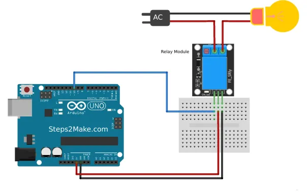
Follow these steps carefully to ensure safe and proper operation:
- Power Connections:
- Connect relay module VCC pin → Arduino 5V pin
- Connect relay module GND pin → Arduino GND pin
- Control Signal:
- Connect relay module IN/INPUT pin → Arduino digital pin (e.g., pin 7)
- Load Connections:
- Connect power source wire → COM terminal
- Connect device wire → NO terminal (for normally-off operation)
- Connect neutral wires directly (bypassing relay for AC circuits)
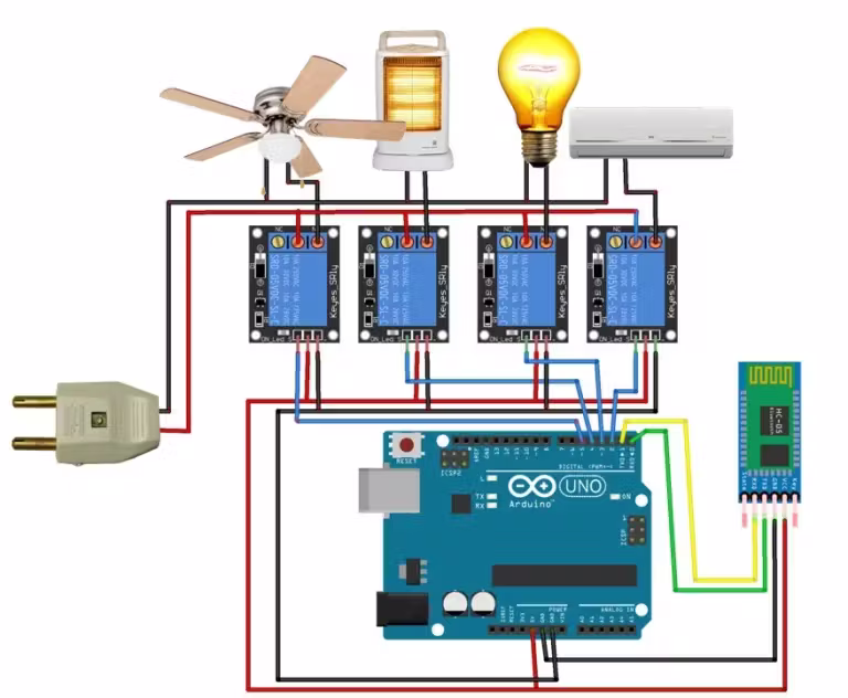
3 Multi-Channel Module Wiring
For 4-channel modules, the principle extends logically:
- Each IN pin connects to a separate Arduino digital pin
- Common power connections (VCC and GND) are shared between all relays
- Each relay channel gets independent load connections
- Consider using a separate power supply for loads drawing significant current
Understanding Relay Module Input Triggers
Relay modules come with two trigger types that determine activation logic:
| Trigger Type | Activation Signal | Default State | Typical Use |
|---|---|---|---|
| High-Level Trigger | Relay activates when control pin receives HIGH signal (5V/3.3V) | Relay OFF when pin is LOW | Standard logic, intuitive for beginners |
| Low-Level Trigger | Relay activates when control pin receives LOW signal (0V) | Relay ON when pin is LOW | Safety applications, failsafe designs |
Most modules include jumpers to select between these modes. The default is often high-level trigger, but always check your module's documentation.
Programming Your Arduino for Relay Control
4 Basic Relay Control Sketch
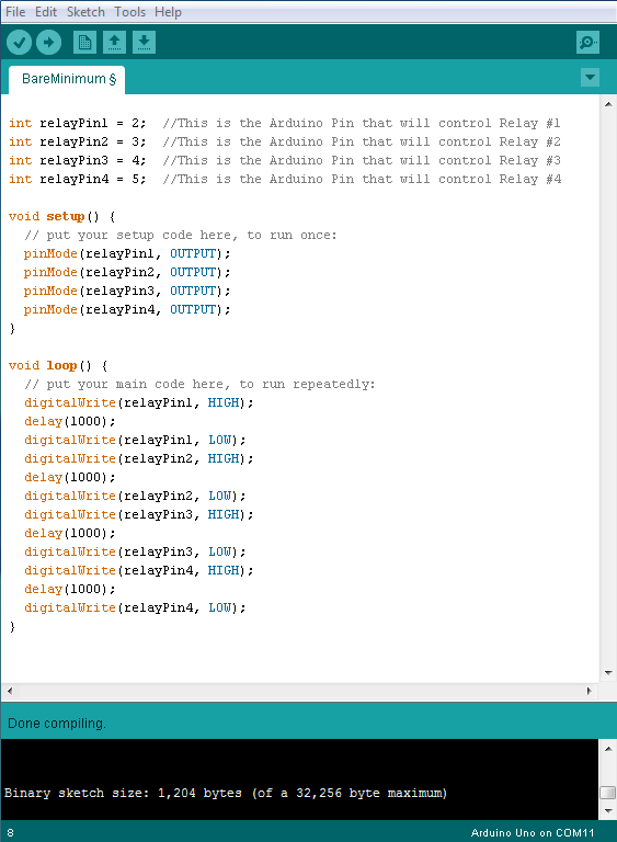
Here's a simple code to turn a relay on and off at 5-second intervals:
#define RELAY_PIN 7  // Digital pin connected to relay

void setup() {
  pinMode(RELAY_PIN, OUTPUT);
  digitalWrite(RELAY_PIN, HIGH);  // Start with relay off
  // Note: Use LOW instead if using low-level trigger module
}

void loop() {
  // Turn relay ON (activates connected device)
  digitalWrite(RELAY_PIN, LOW);   // Use HIGH for low-level trigger modules
  delay(5000);                    // Wait 5 seconds

  // Turn relay OFF (deactivates connected device)
  digitalWrite(RELAY_PIN, HIGH);  // Use LOW for low-level trigger modules
  delay(5000);                    // Wait 5 seconds
}
Code Explanation: This basic example demonstrates relay control fundamentals. The relay toggles every 5 seconds. Remember to invert the logic (HIGH/LOW) if your module uses low-level trigger activation.
5 Advanced Control with Serial Commands
For more interactive control, use this code that accepts commands from the Serial Monitor:
#define RELAY_PIN 7
String inputString = "";
bool relayState = false;

void setup() {
  Serial.begin(9600);
  pinMode(RELAY_PIN, OUTPUT);
  digitalWrite(RELAY_PIN, HIGH);  // Start with relay off
  Serial.println("Relay Control System Ready");
  Serial.println("Commands: '1'=ON, '0'=OFF, 's'=Status");
  Serial.println("---------------------------");
}

void loop() {
  // Check for serial input
  if (Serial.available()) {
    char c = Serial.read();

    if (c == '1') {
      digitalWrite(RELAY_PIN, LOW);
      Serial.println("Relay ON - Device Active");
      relayState = true;
    }
    else if (c == '0') {
      digitalWrite(RELAY_PIN, HIGH);
      Serial.println("Relay OFF - Device Inactive");
      relayState = false;
    }
    else if (c == 's' || c == 'S') {
      Serial.print("Current Relay State: ");
      Serial.println(relayState ? "ON" : "OFF");
    }
    else if (c == '\n') {
      // Ignore newline characters
    }
    else {
      Serial.println("Invalid command. Use: 1, 0, or s");
    }
  }
}
This advanced example allows you to control the relay remotely via serial communication, perfect for testing and debugging.
Practical Project Examples
Automated Light Control
Create a system that turns lights on at dusk using LDR sensor and relay module. Add scheduling for complete automation.
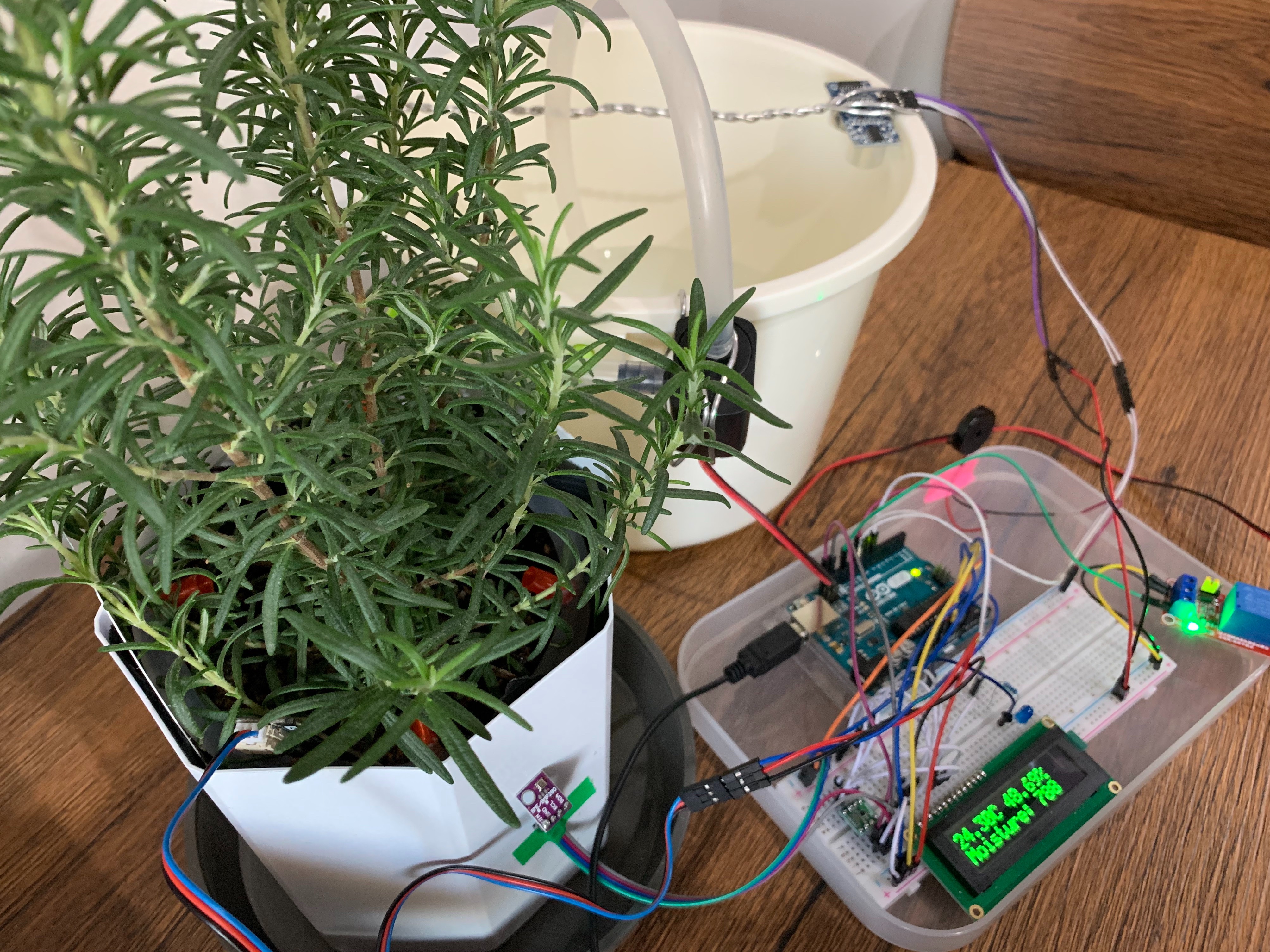
Smart Garden Watering
Control water pump based on soil moisture readings. Relay switches pump while Arduino monitors sensors.
Home Appliance Scheduler
Program specific on/off times for household appliances using Arduino's internal clock or RTC module.
Safety Cut-off System
Use temperature or current sensors to automatically cut power when unsafe conditions are detected.
Troubleshooting Common Issues
6 Common Problems and Solutions
| Symptom | Possible Causes | Solutions |
|---|---|---|
| Relay Not Switching | Incorrect power, wrong trigger type, loose connections | Check power supply, verify trigger logic, test with multimeter |
| Relay Chatter/Buzzing | Voltage spikes, inductive loads, insufficient current | Add snubber circuit, check load type, ensure adequate power |
| Arduino Resets | Power spikes when relay switches, ground loops | Add separate power supply, use decoupling capacitors |
| Relay Sticking/Overheating | Overload, frequent switching, poor heat dissipation | Check load specifications, reduce switching frequency, add heatsink |
Safety Considerations and Best Practices
7 Essential Safety Guidelines
Electrical Safety Measures:
- Always use appropriate wire gauge for your current requirements
- Enclose high-voltage connections in protective, non-conductive boxes
- Install fuses or circuit breakers for overload protection
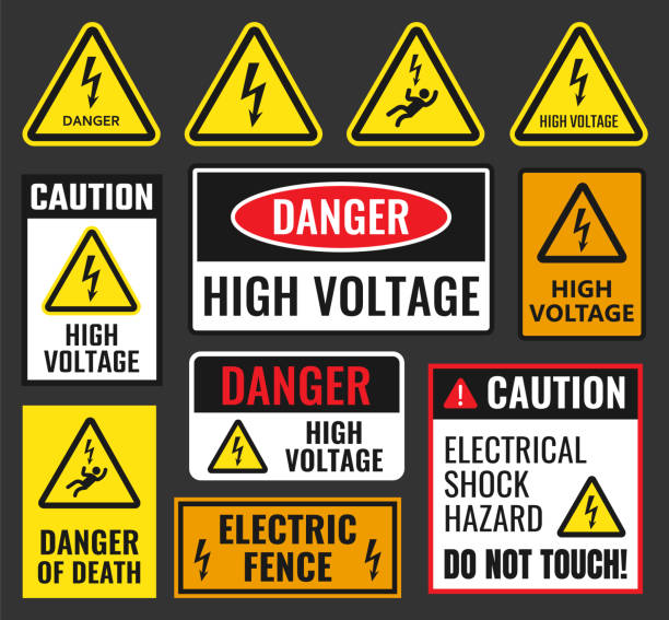
- Clearly label high-voltage sections with warning signs
- Use strain relief on cables to prevent loose connections
Arduino Protection Strategies:
- Use opto-isolated relay modules for complete voltage separation
- Add flyback diodes for inductive loads (motors, solenoids)
- Implement software debouncing to reduce contact arcing
- Use separate power supplies for control and load circuits
- Add TVS diodes for voltage spike protection
Advanced Applications and Integrations
8 IoT Relay Control with ESP8266/ESP32
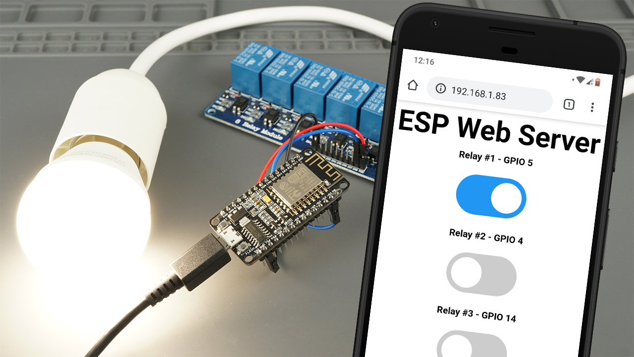
Transform basic relay control into IoT-enabled systems using Wi-Fi capable microcontrollers:
// Example using ESP8266 with Blynk IoT platform #include#include #define RELAY_PIN D1 char auth[] = "YourBlynkAuthToken"; char ssid[] = "YourWiFiNetwork"; char pass[] = "YourWiFiPassword"; // Virtual pin V1 in Blynk app controls the relay BLYNK_WRITE(V1) { int value = param.asInt(); digitalWrite(RELAY_PIN, value); Serial.print("Relay controlled via Blynk: "); Serial.println(value ? "ON" : "OFF"); } void setup() { Serial.begin(115200); pinMode(RELAY_PIN, OUTPUT); digitalWrite(RELAY_PIN, HIGH); // Start OFF Blynk.begin(auth, ssid, pass); Serial.println("Connecting to Blynk..."); } void loop() { Blynk.run(); // Add other logic here }
This example demonstrates cloud-based relay control, allowing you to operate devices from anywhere with internet access.
Optimizing for Energy Efficiency
Use Latching Relays
For battery-powered applications, latching relays consume power only during switching, not while maintaining state.
Implement Sleep Modes
Put Arduino in sleep mode between operations to reduce overall power consumption.
Solar Power Integration
Combine with solar panels and charge controllers for completely off-grid applications.
Power Monitoring
Add current sensors to monitor and optimize energy usage of controlled devices.
Conclusion and Next Steps
Relay modules provide the crucial bridge between the digital world of microcontrollers and the physical world of appliances, motors, and lighting. By mastering relay control with Arduino, you've acquired a fundamental skill for countless automation and IoT projects.
- Build a complete home automation system with multiple relays
- Create a weather-responsive outdoor lighting system
- Design an energy monitoring system with relay-based load shedding
- Develop an industrial prototype with safety interlocks and PLC-like functionality
Final Pro Tip: Always prototype with low-voltage DC loads (like LEDs or small motors) before connecting to mains AC. Document your wiring carefully, and consider creating a wiring diagram for complex projects. Safety should always be your top priority in all electrical projects.