Introduction to I2C OLED Display with Arduino
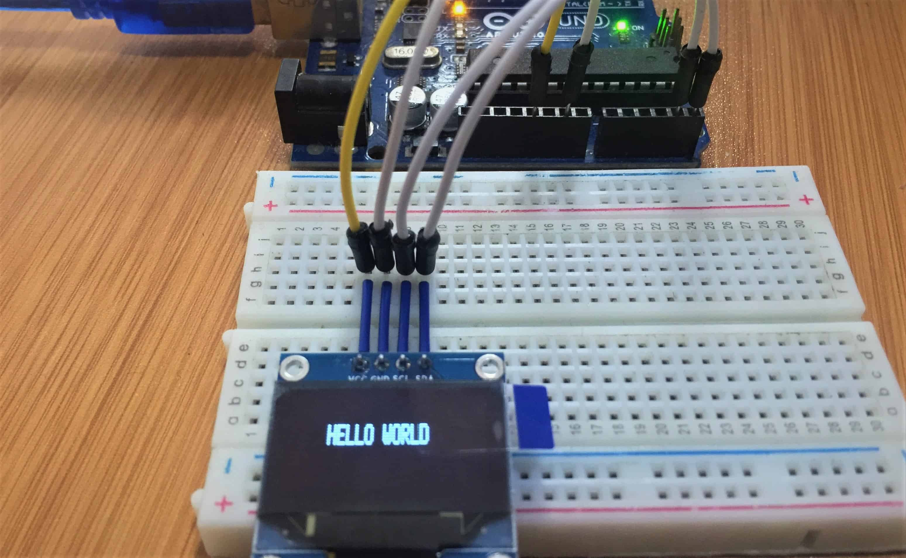
OLED displays have become incredibly popular in the Arduino community for their crisp visuals, excellent contrast, and low power consumption. This comprehensive guide walks you through everything you need to know about using the SSD1306 0.96-inch I2C OLED display with your Arduino board.
Understanding the SSD1306 0.96-inch OLED Display
The Organic Light-Emitting Diode (OLED) display we're focusing on is the SSD1306 model - a monochrome display measuring 0.96 inches diagonally with a resolution of 128×64 pixels.
Unlike LCDs that require a separate backlight, each individual pixel in an OLED emits its own light. This creates two significant advantages:
Perfect Black Levels
When a pixel is off, it emits no light at all, resulting in infinite contrast ratios, especially noticeable in dark environments.
Lower Power Consumption
Pixels only consume energy when they're illuminated, making OLEDs more energy-efficient than always-backlit LCD displays.
What You'll Need for This Tutorial
Before we dive into the connections and code, let's make sure you have all the necessary components:
- Arduino Board (Uno, Nano, Mega, or Leonardo)
- SSD1306 0.96-inch I2C OLED Display
- Breadboard and jumper wires
- USB cable for Arduino programming
- Arduino IDE installed on your computer
Wiring the OLED Display to Arduino
1 Basic Wiring for Arduino Uno
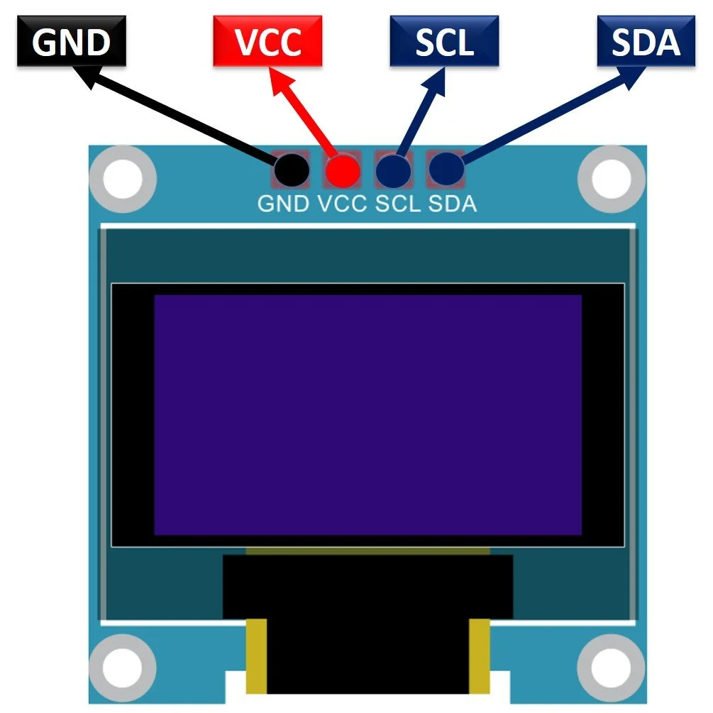
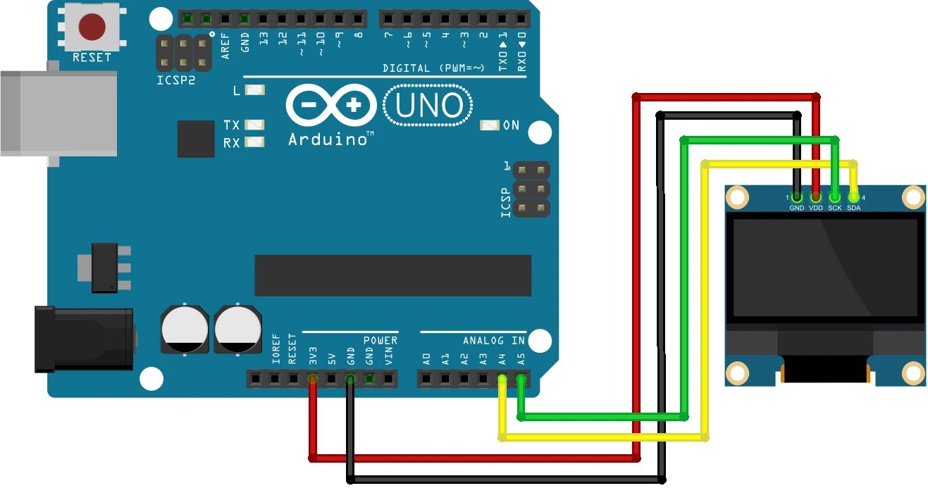
One of the biggest advantages of I2C OLED displays is their simple wiring. With only four connections required:
| OLED Display Pin | Connects to Arduino Uno Pin |
|---|---|
| VCC/Vin | 5V |
| GND | GND |
| SCL (Clock) | A5 |
| SDA (Data) | A4 |
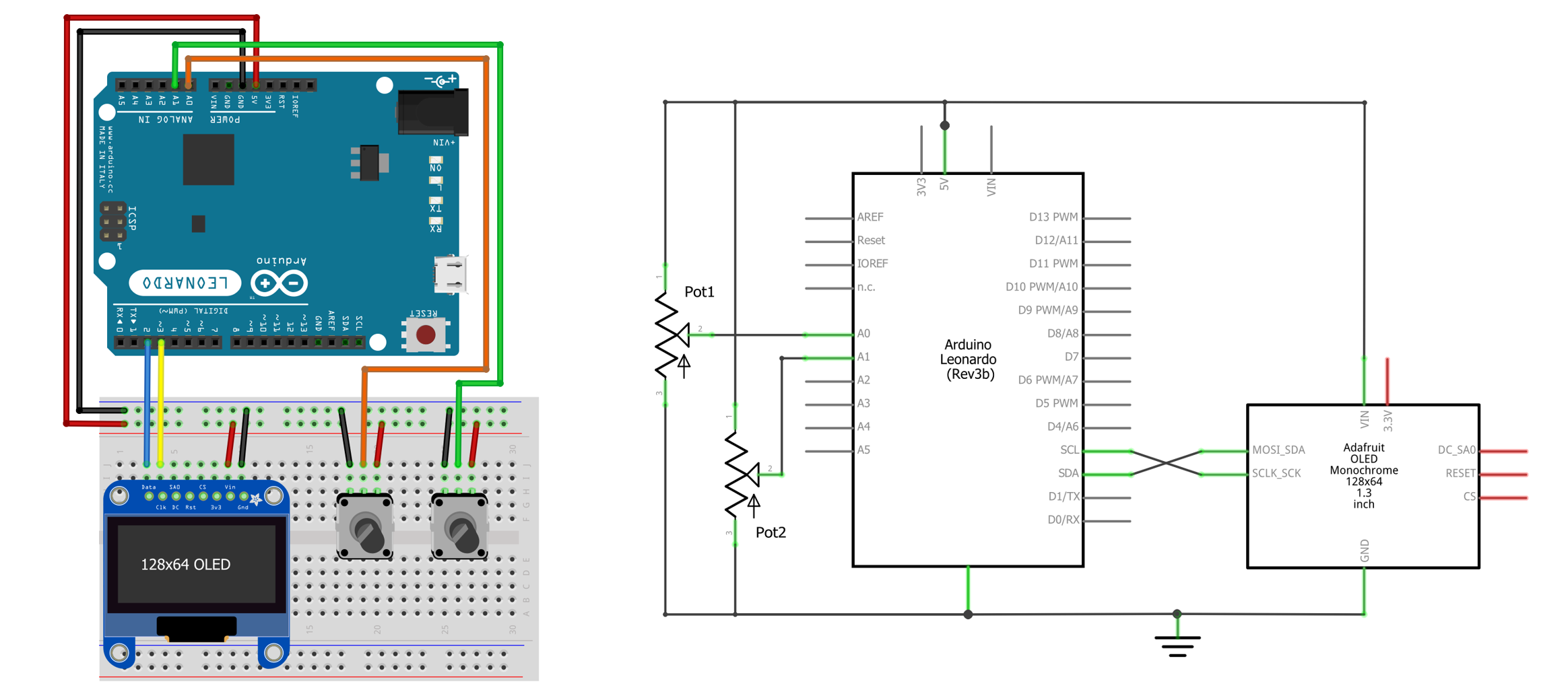
2 I2C Pin Variations for Different Arduino Boards
While the wiring concept remains the same, the specific I2C pins vary between Arduino models:
- Arduino Nano: SDA → A4; SCL → A5
- Arduino Mega: SDA → Digital 20; SCL → Digital 21
- Arduino Leonardo: SDA → Digital 20; SCL → Digital 21
Installing Required Libraries
3 Step-by-Step Library Installation
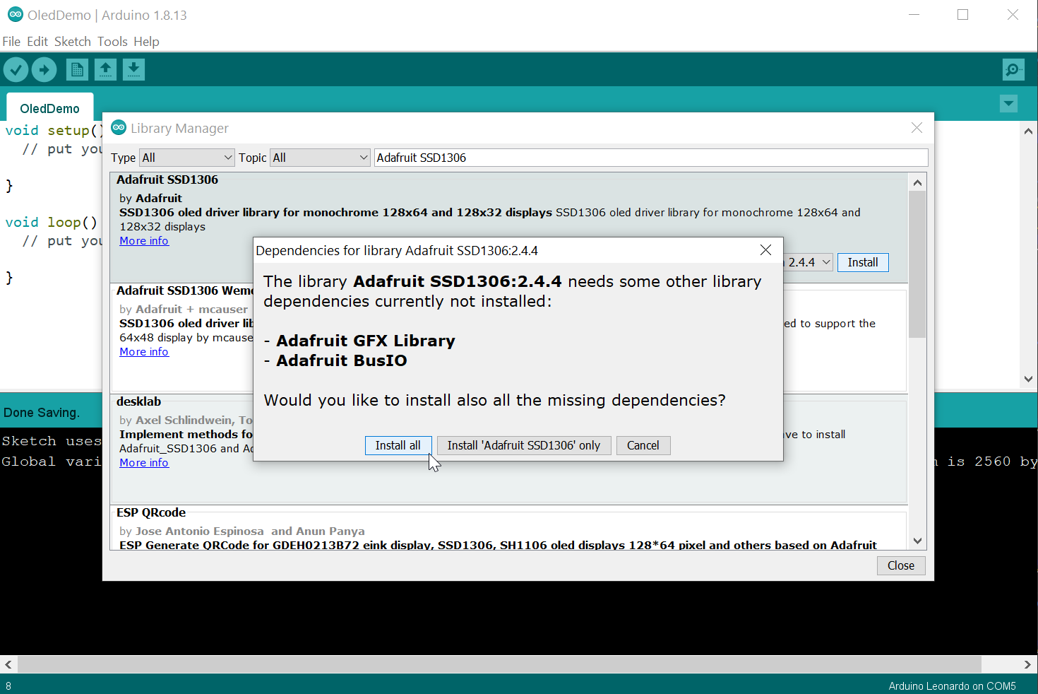
To communicate with the OLED display, we need two essential libraries from Adafruit:
- Open Arduino IDE and navigate to Sketch > Include Library > Manage Libraries
- In the Library Manager, type "SSD1306" in the search box
- Look for "Adafruit SSD1306" by Adafruit Industries and click Install
- Once installed, search for "GFX" in the Library Manager
- Find "Adafruit GFX Library" by Adafruit Industries and click Install
- Restart your Arduino IDE to complete the installation
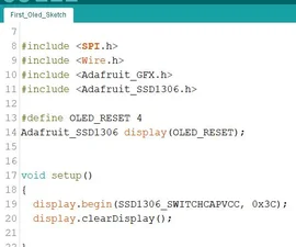
Essential Functions for OLED Control
Display Initialization
display.begin(SSD1306_SWITCHCAPVCC, 0x3C) - Initializes display
display.display() - Updates screen with drawing commands
display.clearDisplay() - Clears entire screen buffer
Text Manipulation
display.setTextSize(n) - Sets font size (1-8)
display.setTextColor(COLOR) - Sets text color
display.setCursor(x, y) - Positions text cursor
display.print("text") - Outputs text to screen
Drawing Functions
display.drawPixel(x, y, COLOR) - Draws single pixel
display.drawLine(x1, y1, x2, y2, COLOR) - Draws line
display.drawRect(x, y, w, h, COLOR) - Draws rectangle
display.drawCircle(x, y, r, COLOR) - Draws circle
Testing Your OLED Display Connection
4 Initial Testing Procedure
Once you've wired your display and installed the libraries, test if everything is working correctly:
- In Arduino IDE, go to File > Examples > Adafruit SSD1306
- Select the example matching your display (usually 128x64 I2C)
- Verify and upload the code to your Arduino
Complete Working Example: Displaying Text and Graphics
5 Basic Display Example
Here's a complete example that demonstrates core OLED functionality:
#include#include #include // Define display dimensions #define SCREEN_WIDTH 128 #define SCREEN_HEIGHT 64 // Define OLED reset pin #define OLED_RESET -1 Adafruit_SSD1306 display(SCREEN_WIDTH, SCREEN_HEIGHT, &Wire, OLED_RESET); void setup() { // Initialize serial communication Serial.begin(115200); // Initialize the OLED display if(!display.begin(SSD1306_SWITCHCAPVCC, 0x3C)) { Serial.println(F("SSD1306 allocation failed")); for(;;); // Don't proceed } // Clear the display buffer display.clearDisplay(); // Display basic text display.setTextSize(1); display.setTextColor(WHITE); display.setCursor(0,0); display.println(F("OLED Display Test")); display.println(F("-----------------")); // Display larger text display.setTextSize(2); display.println(F("Hello!")); // Display a line display.drawLine(0, 30, 128, 30, WHITE); // Display a rectangle display.drawRect(10, 40, 108, 20, WHITE); // Display filled circle display.fillCircle(64, 50, 8, WHITE); // Update the display display.display(); delay(2000); } void loop() { // Empty loop for this example }
Code Explanation: This example demonstrates library inclusion, display initialization with error checking, text display at different sizes, graphical element drawing, and the critical display.display() command that updates the screen.
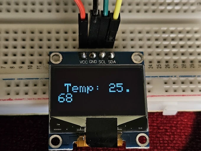
Practical Project: Temperature and Humidity Monitor
6 Complete Project with DHT Sensor
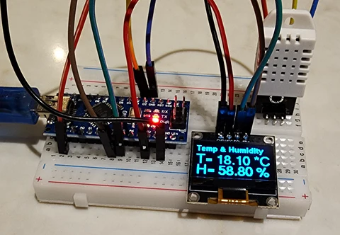
Let's build a practical temperature and humidity monitor using a DHT sensor:
#include#include #include #include // OLED display setup #define SCREEN_WIDTH 128 #define SCREEN_HEIGHT 64 #define OLED_RESET -1 Adafruit_SSD1306 display(SCREEN_WIDTH, SCREEN_HEIGHT, &Wire, OLED_RESET); // DHT sensor setup #define DHTPIN 2 #define DHTTYPE DHT11 DHT dht(DHTPIN, DHTTYPE); void setup() { // Initialize serial communication Serial.begin(115200); // Initialize OLED display if(!display.begin(SSD1306_SWITCHCAPVCC, 0x3C)) { Serial.println(F("OLED allocation failed")); for(;;); } // Initialize DHT sensor dht.begin(); // Clear display display.clearDisplay(); display.display(); delay(2000); } void loop() { // Wait 2 seconds between measurements delay(2000); // Read temperature and humidity float humidity = dht.readHumidity(); float temperature = dht.readTemperature(); // Check if readings failed if (isnan(humidity) || isnan(temperature)) { displayError("Sensor read failed!"); return; } // Update display display.clearDisplay(); // Display title display.setTextSize(1); display.setTextColor(WHITE); display.setCursor(0,0); display.println(F("Env. Monitor")); display.drawLine(0, 10, 128, 10, WHITE); // Display temperature display.setCursor(0, 15); display.setTextSize(2); display.print(F("Temp: ")); display.print(temperature, 1); display.println(F(" C")); // Display humidity display.setCursor(0, 40); display.print(F("Hum: ")); display.print(humidity, 1); display.println(F(" %")); // Update display display.display(); } void displayError(const char* message) { display.clearDisplay(); display.setTextSize(1); display.setTextColor(WHITE); display.setCursor(0,0); display.println(F("ERROR")); display.setCursor(0,20); display.println(message); display.display(); }
This practical example demonstrates how to combine multiple sensors with an OLED display, format and present data in a user-friendly way, add visual indicators based on readings, and implement error handling for robust operation.
Troubleshooting Common Issues
Blank Display
Solution: Check I2C address (try 0x3C or 0x3D), verify wiring, ensure proper voltage, check library installation.
Garbled Display
Solution: Check for loose connections, electrical interference, insufficient power, or incorrect baud rate.
Display Not Recognized
Solution: Ensure libraries are correctly installed, check for I2C address conflicts, verify power supply.
Slow Performance
Solution: Minimize display updates, use partial updates, group drawing commands before calling display().
Next Steps and Advanced Applications
With the foundation established in this guide, consider these advanced project directions:
- Custom Fonts: Use bitmap fonts for unique typography in your displays
- Animation: Create smooth animations by rapidly updating slightly different frames
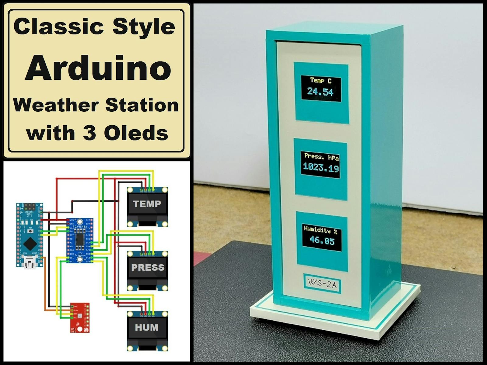
- Multiple Displays: Use different I2C addresses to control multiple OLEDs from one Arduino
- Battery Optimization: Use deep sleep modes between display updates for battery-powered projects
- Menu Systems: Create interactive menus for multi-function projects
- Image Display: Convert and display bitmap images on your OLED