Introduction to ESP32: The Ultimate IoT Development Board
The ESP32 microcontroller has revolutionized IoT development with its powerful features at an affordable price. Developed by Espressif Systems, this versatile chip combines WiFi, Bluetooth, dual-core processing, and extensive peripheral support in a single package. This comprehensive guide will take you from complete beginner to confident ESP32 developer.
Why Choose ESP32 for Your IoT Projects?
The ESP32 stands out in the crowded microcontroller market for several compelling reasons. Unlike simpler boards like Arduino Uno, the ESP32 includes built-in wireless connectivity, making it ideal for Internet of Things applications without requiring additional shields or modules.
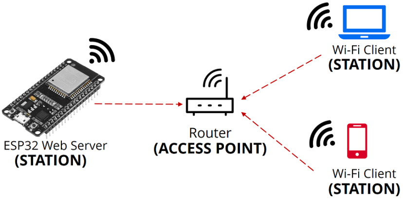
Dual WiFi Modes
Supports both station mode (connects to WiFi) and access point mode (creates its own network) simultaneously.
Bluetooth 4.2
Includes classic Bluetooth and Bluetooth Low Energy (BLE) for energy-efficient wireless communication.
Dual-Core Processor
Two Tensilica LX6 cores running at 240MHz provide substantial processing power for complex applications.
Low Power Consumption
Advanced power management with multiple sleep modes enables battery-powered IoT devices lasting months.
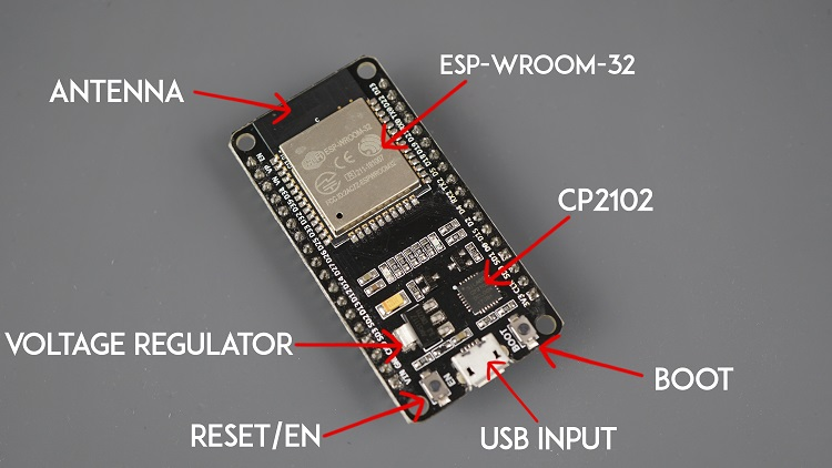
ESP32 Hardware Overview
Understanding the ESP32's hardware capabilities is crucial for effective project development:
- Processor: Dual-core Tensilica LX6 microprocessor up to 240MHz
- Memory: 520KB SRAM, 4MB flash (varies by module)
- Wireless: WiFi 802.11 b/g/n, Bluetooth v4.2 BR/EDR and BLE
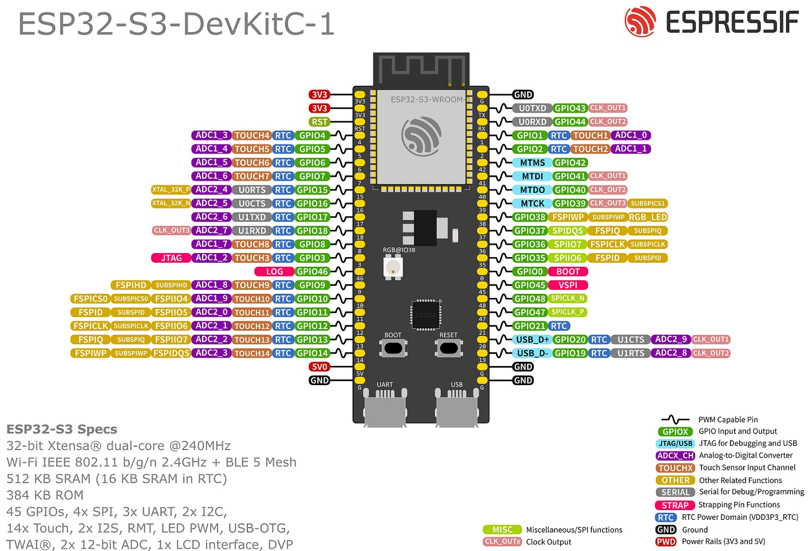
- GPIO: Up to 36 programmable pins with multiple functions
- Sensors: Built-in hall effect sensor, temperature sensor
- Security: Hardware encryption accelerators (SHA, RSA, AES)
ESP32 vs Other Development Boards
| Feature | ESP32 | Arduino Uno | Raspberry Pi Pico |
|---|---|---|---|
| Processor | Dual-core 240MHz | Single-core 16MHz | Dual-core 133MHz |
| Wireless | WiFi + Bluetooth | None (requires shield) | None |
| Memory | 520KB RAM, 4MB Flash | 2KB RAM, 32KB Flash | 264KB RAM, 2MB Flash |
| GPIO Pins | 36 | 14 | 26 |
| Power Consumption | Very Low (sleep modes) | Medium | Low |
| Price Range | $5-$10 | $20-$25 | $4-$5 |
Setting Up Your Development Environment
1 Installing Arduino IDE for ESP32
The easiest way to start programming ESP32 is using the Arduino IDE with ESP32 board support:
- Download Arduino IDE: Get the latest version from arduino.cc (version 1.8.13 or higher recommended)
- Open Preferences: Go to File → Preferences and add to Additional Boards Manager URLs:
https://raw.githubusercontent.com/espressif/arduino-esp32/gh-pages/package_esp32_index.json
- Install ESP32 Boards: Go to Tools → Board → Boards Manager, search for "ESP32", and install
- Select Board: Choose your specific ESP32 board (ESP32 Dev Module is a safe default)
- Install USB Driver: For Windows, install CP210x or CH340 drivers based on your board
2 First ESP32 Program: Blink LED
Test your setup with the classic "Hello World" of hardware - blinking an LED:
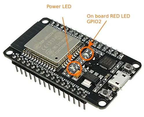
// ESP32 Blink Example
// Most ESP32 boards have built-in LED on GPIO2

void setup() {
  pinMode(2, OUTPUT); // Initialize GPIO2 as output
}

void loop() {
  digitalWrite(2, HIGH); // Turn LED on
  delay(1000);           // Wait 1 second
  digitalWrite(2, LOW);  // Turn LED off
  delay(1000);           // Wait 1 second
}
Upload Instructions: Connect ESP32 via USB, select correct COM port, upload the code. The onboard LED (usually blue) should start blinking at 1-second intervals.
Essential ESP32 Programming Concepts
3 GPIO Control and Input Reading
ESP32 GPIO pins are more versatile than traditional Arduino pins. Here's how to use them effectively:
// Complete GPIO Input/Output Example
const int ledPin = 2;    // GPIO2 for LED output
const int buttonPin = 4; // GPIO4 for button input
const int analogPin = 34; // GPIO34 for analog input (ADC1)

void setup() {
  Serial.begin(115200);

  // Configure pins
  pinMode(ledPin, OUTPUT);
  pinMode(buttonPin, INPUT_PULLUP); // Use internal pull-up resistor

  // Note: ESP32 has 18 ADC channels (ADC1: GPIO32-39, ADC2: GPIO0,2,4,12-15)
}

void loop() {
  // Digital read
  int buttonState = digitalRead(buttonPin);

  // Analog read (12-bit ADC, 0-4095)
  int analogValue = analogRead(analogPin);

  // Control LED based on button
  if (buttonState == LOW) {
    digitalWrite(ledPin, HIGH);
  } else {
    digitalWrite(ledPin, LOW);
  }

  // Print values to serial monitor
  Serial.print("Button: ");
  Serial.print(buttonState);
  Serial.print(" | Analog: ");
  Serial.println(analogValue);

  delay(100); // Short delay
}
Key Points: ESP32 includes internal pull-up/pull-down resistors, 12-bit ADC (vs 10-bit on Arduino), and some pins have special functions (touch, DAC, etc.).
WiFi Connectivity with ESP32
4 Connecting to WiFi Network
ESP32's built-in WiFi makes IoT projects accessible. Here's a complete WiFi connection example:
#include <WiFi.h>

// Replace with your network credentials
const char* ssid = "YOUR_WIFI_NAME";
const char* password = "YOUR_WIFI_PASSWORD";

void setup() {
  Serial.begin(115200);

  // Connect to WiFi
  WiFi.begin(ssid, password);
  Serial.print("Connecting to WiFi");

  while (WiFi.status() != WL_CONNECTED) {
    delay(500);
    Serial.print(".");
  }

  Serial.println();
  Serial.println("WiFi connected!");
  Serial.print("IP address: ");
  Serial.println(WiFi.localIP());
}

void loop() {
  // Check WiFi connection status
  if (WiFi.status() == WL_CONNECTED) {
    Serial.println("WiFi still connected");
  } else {
    Serial.println("WiFi disconnected. Attempting reconnection...");
    WiFi.reconnect();
  }

  delay(10000); // Check every 10 seconds
}
Application: This foundation enables web servers, API calls, MQTT communication, and cloud connectivity for your IoT projects.
Creating a Web Server with ESP32
5 ESP32 as Web Server
Transform your ESP32 into a web server to control devices remotely through a browser:
#include <WiFi.h>
#include <WebServer.h>

// WiFi credentials
const char* ssid = "YOUR_WIFI";
const char* password = "YOUR_PASSWORD";

WebServer server(80); // Create server on port 80

// HTML page
const char MAIN_page[] PROGMEM = R"rawliteral(
<!DOCTYPE html>
<html>
<head>
  <title>ESP32 Web Server</title>
  <meta name="viewport" content="width=device-width, initial-scale=1">
</head>
<body>
  <h1>ESP32 Web Server</h1>
  <p>LED Control:</p>
  <a href="/ledOn"><button>LED ON</button></a>
  <a href="/ledOff"><button>LED OFF</button></a>
</body>
</html>
)rawliteral";

// Handle root URL
void handleRoot() {
  server.send(200, "text/html", MAIN_page);
}

// Handle LED ON
void handleLEDOn() {
  digitalWrite(2, HIGH);
  server.send(200, "text/plain", "LED turned ON");
}

// Handle LED OFF
void handleLEDOff() {
  digitalWrite(2, LOW);
  server.send(200, "text/plain", "LED turned OFF");
}

void setup() {
  Serial.begin(115200);
  pinMode(2, OUTPUT);

  // Connect to WiFi
  WiFi.begin(ssid, password);
  while (WiFi.status() != WL_CONNECTED) {
    delay(1000);
    Serial.println("Connecting to WiFi...");
  }

  Serial.print("IP address: ");
  Serial.println(WiFi.localIP());

  // Define server routes
  server.on("/", handleRoot);
  server.on("/ledOn", handleLEDOn);
  server.on("/ledOff", handleLEDOff);

  server.begin();
  Serial.println("HTTP server started");
}

void loop() {
  server.handleClient(); // Handle client requests
}
Usage: After uploading, check Serial Monitor for IP address, then open that address in any web browser to control the LED remotely.
Bluetooth Communication with ESP32
6 Bluetooth Classic Serial Example
ESP32 supports both Bluetooth Classic and BLE. Here's a simple Bluetooth serial communication example:
#include "BluetoothSerial.h"

BluetoothSerial SerialBT;

void setup() {
  Serial.begin(115200);
  SerialBT.begin("ESP32_Bluetooth"); // Bluetooth device name

  Serial.println("Bluetooth Started! Ready to pair...");
  Serial.println("Device name: ESP32_Bluetooth");
}

void loop() {
  // Read from Bluetooth and send to Serial
  if (SerialBT.available()) {
    char incomingChar = SerialBT.read();
    Serial.write(incomingChar);

    // Echo back to Bluetooth
    SerialBT.write(incomingChar);
  }

  // Read from Serial and send to Bluetooth
  if (Serial.available()) {
    char incomingChar = Serial.read();
    SerialBT.write(incomingChar);
  }

  delay(20);
}
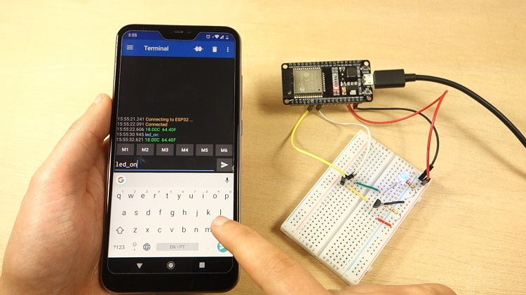
Testing: Pair with your ESP32 from a smartphone using a Bluetooth terminal app (like "Serial Bluetooth Terminal" on Android). Any text you send will be echoed back.
Practical IoT Project: Temperature Monitor
7 Complete IoT Temperature Monitor
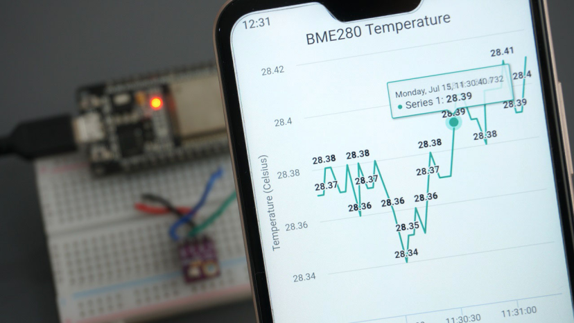
Combine WiFi and sensor reading to create a practical temperature monitoring system:
#include <WiFi.h>
#include <WebServer.h>
#include "DHT.h"

#define DHTPIN 4      // GPIO4 for DHT sensor
#define DHTTYPE DHT22 // DHT22 (AM2302)

DHT dht(DHTPIN, DHTTYPE);

// WiFi credentials
const char* ssid = "YOUR_WIFI";
const char* password = "YOUR_PASSWORD";

WebServer server(80);

float temperature, humidity;

void readSensor() {
  humidity = dht.readHumidity();
  temperature = dht.readTemperature();

  if (isnan(humidity) || isnan(temperature)) {
    Serial.println("Failed to read from DHT sensor!");
    return;
  }
}

void handleRoot() {
  readSensor();

  String html = "<!DOCTYPE html><html><head><meta name='viewport' content='width=device-width, initial-scale=1'>";
  html += "<title>ESP32 Temperature Monitor</title></head><body>";
  html += "<h1>Temperature Monitoring System</h1>";
  html += "<h2>Temperature: " + String(temperature) + "°C</h2>";
  html += "<h2>Humidity: " + String(humidity) + "%</h2>";
  html += "<p><a href='/update'>Refresh</a></p>";
  html += "</body></html>";

  server.send(200, "text/html", html);
}

void setup() {
  Serial.begin(115200);
  dht.begin();

  // Connect to WiFi
  WiFi.begin(ssid, password);
  while (WiFi.status() != WL_CONNECTED) {
    delay(1000);
    Serial.print(".");
  }

  Serial.println("");
  Serial.println("WiFi connected");
  Serial.println("IP address: ");
  Serial.println(WiFi.localIP());

  server.on("/", handleRoot);
  server.on("/update", handleRoot);

  server.begin();
  Serial.println("HTTP server started");
}

void loop() {
  server.handleClient();
  delay(2000); // Update reading every 2 seconds
}
Hardware Setup: Connect DHT22 sensor: VCC to 3.3V, GND to GND, Data to GPIO4. Install "DHT sensor library" by Adafruit via Library Manager.
ESP32 Power Management
8 Deep Sleep for Battery Operation
ESP32's deep sleep mode dramatically reduces power consumption for battery-powered applications:
// ESP32 Deep Sleep Example
// Current consumption drops to ~10μA in deep sleep
// GPIO16 must be connected to RST for wakeup from timer

#define uS_TO_S_FACTOR 1000000  // Conversion factor micro seconds to seconds
#define TIME_TO_SLEEP  30        // Time ESP32 will sleep (seconds)

void setup() {
  Serial.begin(115200);
  Serial.println("ESP32 Deep Sleep Example");

  // Configure wakeup sources
  esp_sleep_enable_timer_wakeup(TIME_TO_SLEEP * uS_TO_S_FACTOR);

  Serial.println("Going to sleep now");
  Serial.flush(); // Ensure all serial data is sent

  // Enter deep sleep
  esp_deep_sleep_start();
}

void loop() {
  // This will never run - ESP32 restarts after deep sleep
}
Important: For timer wakeup, connect GPIO16 to RST pin. In deep sleep, most of the ESP32 is powered off, with only RTC controller active.
Troubleshooting Common ESP32 Issues
Upload Failed
Solution: Hold BOOT button during upload, check COM port, install correct USB drivers (CH340/CP210x), try lower upload speed.
WiFi Not Connecting
Solution: Verify credentials, check 2.4GHz network (ESP32 doesn't support 5GHz), move closer to router, check firewall settings.
GPIO Not Working
Solution: Some pins have restrictions (input-only, used for flash, etc.). Refer to pinout guide, avoid GPIO0,2,4,12,15 during boot.
Power Issues
Solution: Use stable 3.3V power supply (not Arduino 5V), add 100-470μF capacitor near ESP32 power pins, ensure adequate current (500mA+).
Advanced Topics and Next Steps
Once you've mastered the basics, explore these advanced ESP32 capabilities:
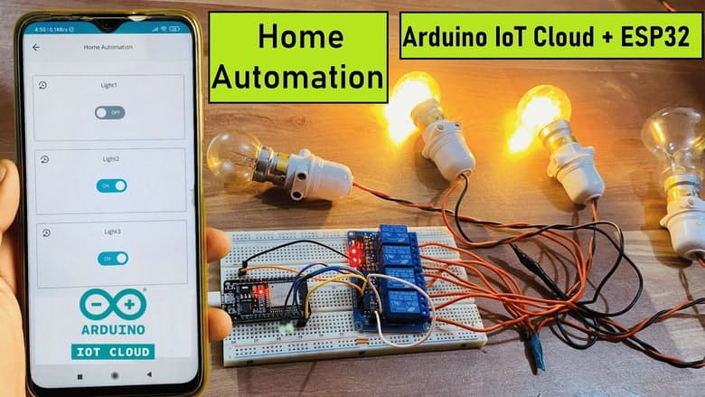
- MQTT Communication: Connect to home automation systems like Home Assistant
- Over-the-Air Updates: Deploy new firmware wirelessly (OTA)
- Dual-Core Programming: Use FreeRTOS to run tasks on both CPU cores simultaneously
- WebSocket Communication: Real-time bidirectional web communication
- MicroPython: Program ESP32 using Python instead of C++
- ESP-NOW Protocol: Direct ESP32-to-ESP32 communication without WiFi router
Recommended ESP32 Development Boards
| Board | Key Features | Best For | Price |
|---|---|---|---|
| ESP32 DevKit V1 | Standard layout, CP2102 USB, breadboard-friendly | Beginners, general projects | $6-$8 |
| NodeMCU-32S | Built-in programmer, Lua support, many GPIO | WiFi projects, MicroPython | $7-$10 |
| ESP32-CAM | Camera module, microSD slot, small size | Video streaming, face recognition | $8-$12 |
| TTGO T-Display | Built-in ST7789 display, battery connector | Portable projects, data visualization | $12-$15 |
| FireBeetle ESP32 | Ultra-low power, deep sleep, compact design | Battery projects, wearables | $10-$13 |