Introduction to Wireless Motor Control
In today's world of robotics and automation, wireless control systems have become increasingly important. This comprehensive tutorial will guide you through creating a Bluetooth-controlled DC motor system using Arduino. Whether you're building a robot, a smart vehicle, or any motorized project, this guide provides the knowledge to implement wireless control efficiently.
Project Overview and Components
What You'll Build
This project creates a system where you can control two DC motors wirelessly using Bluetooth communication. The Arduino board serves as the brain, processing commands received via Bluetooth and controlling the motors accordingly through a motor driver module.
Required Components
To complete this project, you'll need the following components:
Arduino Board
Uno, Nano, or similar microcontroller board
HC-05/06 Bluetooth Module
For wireless communication with smartphones or computers
L298N Motor Driver
Dual H-bridge driver for controlling two DC motors
Two DC Motors
6-12V gear motors recommended for robotics projects
Power Supply
Appropriate voltage and current for your motors (typically 7-12V, 2A)
Breadboard & Wires
For prototyping and connections
Chassis & Wheels
For building a complete robot vehicle (optional)
Battery Holder
To power your mobile robot project
Understanding the Key Components
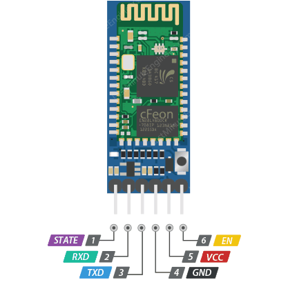
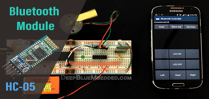
1 HC-05 Bluetooth Module
The HC-05 is a popular Bluetooth module that operates as a Serial Port Protocol (SPP) device, creating a transparent wireless serial connection. It can operate in both master and slave modes, though for this project, we'll use it in slave mode to receive commands from a smartphone or computer.
Key Specifications:
- Operating Voltage: 3.6V - 6V (typically used with 5V)
- Communication: Serial communication at 9600 baud (default)
- Range: Approximately 10 meters (30 feet) in open space
- Pairing: Default pairing code is "1234" or "0000"
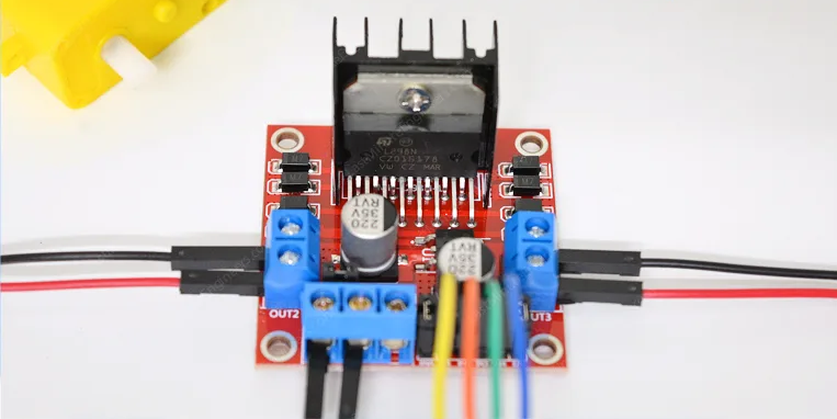
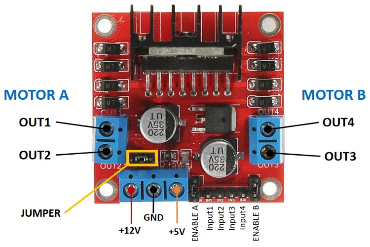
2 L298N Motor Driver Module
The L298N is a dual H-bridge motor driver that allows you to control the direction and speed of two DC motors independently. It can handle significant current (up to 2A per bridge) and includes built-in protection diodes.
Key Features:
- Dual H-bridge design for bidirectional motor control
- Maximum current: 2A per bridge (3A peak)
- Operating voltage: 5V to 35V for motors
- Built-in 5V regulator (can power Arduino with small motors)
- Heat sink and protection diodes included
Circuit Connection Guide
3 Step-by-Step Wiring Instructions
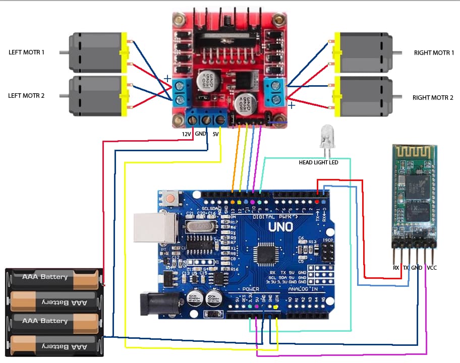
Proper wiring is crucial for the success of this project. Follow these connections carefully:
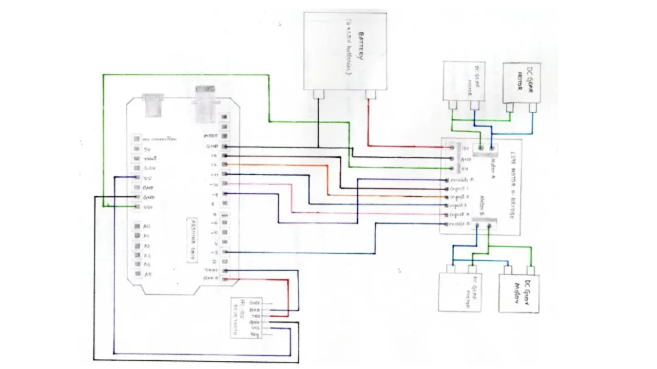
Arduino to L298N Connections:
- Arduino Pin 5 → L298N IN1
- Arduino Pin 6 → L298N IN2
- Arduino Pin 9 → L298N IN3
- Arduino Pin 10 → L298N IN4
- Arduino 5V → L298N +5V
- Arduino GND → L298N GND
Motor Connections to L298N:
- Motor A terminals → L298N OUT1 and OUT2
- Motor B terminals → L298N OUT3 and OUT4
Power Connections:
- External power supply positive → L298N +12V input
- External power supply negative → L298N GND
Bluetooth Module Connections:
- HC-05 VCC → Arduino 5V
- HC-05 GND → Arduino GND
- HC-05 TX → Arduino Pin 0 (RX)
- HC-05 RX → Arduino Pin 1 (TX)
Arduino Code Implementation
4 Complete Control Sketch
Below is the complete Arduino sketch that enables Bluetooth control of two DC motors:
// Define motor control pins
const int motorA1 = 5;
const int motorA2 = 6;
const int motorB1 = 9;
const int motorB2 = 10;

// Variable to store incoming Bluetooth data
char data = 0;

void setup() {
  // Initialize motor control pins as outputs
  pinMode(motorA1, OUTPUT);
  pinMode(motorA2, OUTPUT);
  pinMode(motorB1, OUTPUT);
  pinMode(motorB2, OUTPUT);

  // Initialize serial communication for Bluetooth
  Serial.begin(9600);

  // Initially stop all motors
  stopMotors();

  Serial.println("Bluetooth Motor Control Ready");
  Serial.println("Send commands: F, B, L, R, S");
}

void loop() {
  // Check if data is available from Bluetooth
  if (Serial.available() > 0) {
    data = Serial.read(); // Read incoming data
    Serial.print("Received: ");
    Serial.println(data);

    // Process the received command
    switch(data) {
      case 'F': // Move Forward
        forward();
        break;
      case 'B': // Move Backward
        backward();
        break;
      case 'L': // Turn Left
        left();
        break;
      case 'R': // Turn Right
        right();
        break;
      case 'S': // Stop
        stopMotors();
        break;
      default:
        // Ignore unrecognized commands
        break;
    }
  }
}

// Motor control functions
void forward() {
  digitalWrite(motorA1, HIGH);
  digitalWrite(motorA2, LOW);
  digitalWrite(motorB1, HIGH);
  digitalWrite(motorB2, LOW);
  Serial.println("Moving Forward");
}

void backward() {
  digitalWrite(motorA1, LOW);
  digitalWrite(motorA2, HIGH);
  digitalWrite(motorB1, LOW);
  digitalWrite(motorB2, HIGH);
  Serial.println("Moving Backward");
}

void left() {
  digitalWrite(motorA1, LOW);
  digitalWrite(motorA2, HIGH);
  digitalWrite(motorB1, HIGH);
  digitalWrite(motorB2, LOW);
  Serial.println("Turning Left");
}

void right() {
  digitalWrite(motorA1, HIGH);
  digitalWrite(motorA2, LOW);
  digitalWrite(motorB1, LOW);
  digitalWrite(motorB2, HIGH);
  Serial.println("Turning Right");
}

void stopMotors() {
  digitalWrite(motorA1, LOW);
  digitalWrite(motorA2, LOW);
  digitalWrite(motorB1, LOW);
  digitalWrite(motorB2, LOW);
  Serial.println("Stopped");
}
Bluetooth Control Setup
5 Configuring Your Control Device
Smartphone Control Options:
Android Apps
Serial Bluetooth Terminal, Arduino Bluetooth Controller, or custom apps
iOS Apps
BlueTerm, LightBlue, or Blynk for custom interfaces
Computer Control
Arduino Serial Monitor, CoolTerm, Putty, or custom Python scripts
Custom Interfaces
MIT App Inventor, Blynk, or Android Studio for custom control apps
Pairing Process:
- Power your Arduino circuit
- Enable Bluetooth on your smartphone/computer
- Scan for available devices
- Look for "HC-05" and pair with it (default PIN is "1234")
- Open your serial terminal app and connect to the HC-05 module
Advanced Features and Modifications
6 Adding Speed Control with PWM
To control motor speed, modify the code to use PWM (Pulse Width Modulation) on the enable pins of the L298N:
// Additional PWM pins for speed control
const int enableA = 3;
const int enableB = 11;

// Speed variable (0-255)
int motorSpeed = 150;

void setup() {
  // Previous setup code...
  pinMode(enableA, OUTPUT);
  pinMode(enableB, OUTPUT);

  // Set initial speed
  analogWrite(enableA, motorSpeed);
  analogWrite(enableB, motorSpeed);
}

// Add speed control commands to loop()
if (data == '+') {
  motorSpeed = min(motorSpeed + 20, 255);
  updateSpeed();
}
if (data == '-') {
  motorSpeed = max(motorSpeed - 20, 0);
  updateSpeed();
}

void updateSpeed() {
  analogWrite(enableA, motorSpeed);
  analogWrite(enableB, motorSpeed);
  Serial.print("Speed set to: ");
  Serial.println(motorSpeed);
}
This modification allows you to control motor speed by sending '+' to increase speed and '-' to decrease speed via Bluetooth.
Troubleshooting Common Issues
Motors Not Moving
Solution: Check power connections, verify motor driver enable jumpers are in place, test motors directly with power supply, check for loose connections.
Bluetooth Connection Issues
Solution: Ensure HC-05 is in pairing mode (LED blinking rapidly), check if module is already paired to another device, verify baud rate matches (9600).
System Resets When Motors Start
Solution: Use separate power supplies for Arduino and motors, add large capacitor (1000µF) across motor power input, check battery voltage under load.
Wrong Motor Direction
Solution: Swap motor wires on the driver outputs or modify code to reverse pin logic in motor control functions.
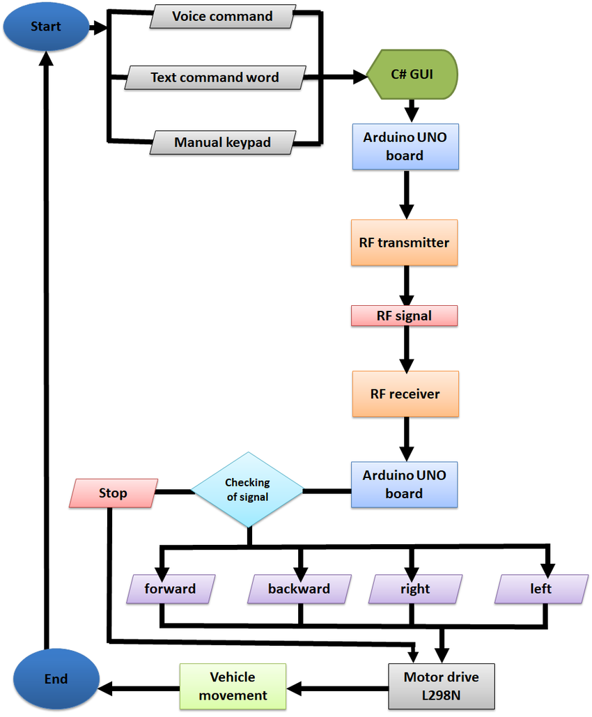
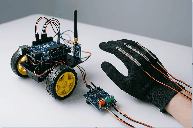
Project Applications and Extensions
7 Practical Implementations
Bluetooth Robot Car
Complete mobile robot with wireless control via smartphone
Smart Home Devices
Control curtains, blinds, or other motorized home fixtures
Educational Demonstrations
Perfect for teaching robotics, programming, and electronics
Assistive Technology
Create devices to help people with mobility challenges
8 Enhancing Your Project
Advanced Project Ideas:
- Wireless Camera: Implement FPV (First Person View) using a Wi-Fi camera module
- Voice Control: Integrate with Google Assistant or Alexa for voice commands
- Autonomous Features: Add ultrasonic sensors for obstacle avoidance
- Internet Connectivity: Add ESP8266 for control from anywhere via the internet
- Multiple Control Modes: Implement joystick control, gesture control, or path recording
Safety Considerations and Best Practices
Electrical Safety
Always double-check connections before powering, use appropriate fuses for motor circuits, keep high-current wiring separated from signal wiring.
Mechanical Safety
Secure all components properly to prevent shorts, add bumpers or sensors to prevent collisions, implement emergency stop functionality.
Thermal Management
Ensure proper ventilation for motor driver modules, monitor temperature during extended use, consider adding heat sinks if needed.
Operational Safety
Test in controlled environments first, keep loose clothing and hair away from moving parts, supervise operation of autonomous systems.
Conclusion
This comprehensive guide has covered everything you need to successfully control two DC motors using Arduino and Bluetooth. From component selection and circuit wiring to programming and troubleshooting, you now have the knowledge to implement this versatile wireless control system in your own projects.
The skills learned here form a foundation for countless robotics and automation projects. As you become more comfortable with these concepts, you can expand your projects with additional sensors, more complex control algorithms, or integration with other technologies like IoT platforms or AI-based control systems.
