Prerequisites: Setting Up Your Environment
Before we start working with the ESP32's GPIO pins, you need to have the Arduino IDE properly configured. Make sure you've installed the ESP32 boards add-on through the Boards Manager. This is essential for compiling and uploading code to your ESP32 development board.
Controlling Digital Outputs with ESP32
Digital outputs allow your ESP32 to control external components like LEDs, relays, or buzzers. The process is straightforward but requires proper initialization.
1 Configuring Output Pins
First, you need to configure the GPIO pin as an output using the pinMode() function:
pinMode(GPIO, OUTPUT);
Once configured as an output, you can control the pin's state using the digitalWrite() function:
digitalWrite(GPIO, STATE);
The STATE parameter can be either HIGH (3.3V) or LOW (0V).
Reading Digital Inputs with ESP32
Digital inputs allow your ESP32 to sense the state of external devices like buttons, switches, or digital sensors. Setting up a digital input follows a similar pattern to outputs.
2 Configuring Input Pins
First, configure the GPIO pin as an input:
pinMode(GPIO, INPUT);
To read the current state of the pin, use the digitalRead() function:
digitalRead(GPIO);
This function returns either HIGH or LOW depending on the voltage detected at the pin.
Practical Project: Button-Controlled LED
Let's put these concepts into practice with a simple yet educational project. We'll create a circuit where an LED lights up only when a pushbutton is pressed. This demonstrates both digital input reading and output control in a single application.
3 Schematic Diagram and Required Components
Before writing any code, you need to assemble the circuit. We'll connect an LED to GPIO 5 and a pushbutton to GPIO 4.
Parts Required:
- ESP32 development board (DOIT ESP32 DEVKIT V1 recommended)
- LED (any color)
- Pushbutton
- 220Ω resistor (for the LED)
- 10kΩ resistor (pull-down for the button)
- Breadboard and jumper wires
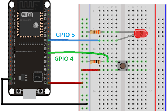
4 Circuit Assembly Instructions
- Connect one side of the pushbutton to GPIO 4
- Connect the same button side to 3.3V through the 10kΩ pull-down resistor
- Connect the opposite button side to ground
- Connect the LED's anode (longer leg) to GPIO 5 through the 220Ω current-limiting resistor
- Connect the LED's cathode (shorter leg) directly to ground
This configuration ensures the button pin reads LOW when not pressed (pulled down to ground through the resistor) and HIGH when pressed (connected to 3.3V).
Complete Arduino Code
Here's the complete code for our button-controlled LED project. Copy this into your Arduino IDE:
                    // Set pin numbers
                    const int buttonPin = 4;  // Pushbutton connected to GPIO 4
                    const int ledPin = 5;     // LED connected to GPIO 5

                    // Variable for storing pushbutton status
                    int buttonState = 0;

                    void setup() {
                    Serial.begin(115200);

                    // Initialize pushbutton pin as input
                    pinMode(buttonPin, INPUT);

                    // Initialize LED pin as output
                    pinMode(ledPin, OUTPUT);
                    }

                    void loop() {
                    // Read the state of pushbutton
                    buttonState = digitalRead(buttonPin);

                    // Print button state to Serial Monitor for debugging
                    Serial.println(buttonState);

                    // Check if pushbutton is pressed
                    if (buttonState == HIGH) {
                        // Turn LED ON
                        digitalWrite(ledPin, HIGH);
                    } else {
                        // Turn LED OFF
                        digitalWrite(ledPin, LOW);
                    }
                    }
Code Explanation: Step by Step
5 Pin Assignment
                        const int buttonPin = 4;
                        const int ledPin = 5;
These constants define which GPIO pins connect to our button and LED. Using constants makes the code more readable and easier to modify.
6 Setup Function
                        void setup() {
                        Serial.begin(115200);
                        pinMode(buttonPin, INPUT);
                        pinMode(ledPin, OUTPUT);
                        }
The setup() function runs once when the ESP32 starts. Serial.begin(115200) initializes serial communication for debugging, and pinMode() configures the button pin as input and LED pin as output.
7 Main Loop
                        void loop() {
                        buttonState = digitalRead(buttonPin);
                        Serial.println(buttonState);

                        if (buttonState == HIGH) {
                            digitalWrite(ledPin, HIGH);
                        } else {
                            digitalWrite(ledPin, LOW);
                        }
                        }
The loop() function runs continuously, reading the button state with digitalRead(), printing to the Serial Monitor, and controlling the LED based on the button state.
Uploading Code to ESP32
Follow these steps to upload the code to your ESP32:
- Select Board: Go to Tools > Board and select your ESP32 board (e.g., DOIT ESP32 DEVKIT V1)
- Select Port: Go to Tools > Port and choose the COM port where your ESP32 is connected
- Upload: Click the upload button (right arrow) and wait for "Done uploading" message
Understanding Pull-Down Resistors
You might wonder why we need the 10kΩ resistor connected to the button. This is called a pull-down resistor, and it serves two crucial purposes:
- Defines Default State: When the button isn't pressed, the GPIO pin is connected to ground through the resistor, ensuring it reads a definite LOW state instead of floating unpredictably
- Limits Current: When the button is pressed, the resistor limits the current flowing from 3.3V to the GPIO pin, protecting both the pin and the power supply
Without this resistor, the pin would be "floating" when the button isn't pressed, potentially reading random HIGH and LOW values due to electromagnetic interference.
Advanced Considerations
8 Using Internal Pull-Up Resistors
The ESP32 has built-in pull-up resistors that you can enable in software, eliminating the need for an external pull-down resistor in some cases:
pinMode(buttonPin, INPUT_PULLUP);
With this configuration, the button would be wired differently (one side to GPIO pin, the other to ground), and the logic in your code would be inverted (button press = LOW, not pressed = HIGH).
9 Input-Only Pins
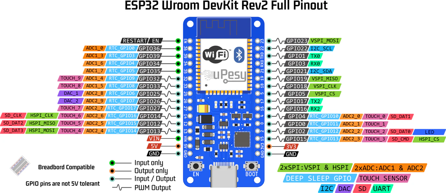
Remember that GPIOs 34, 35, 36, and 39 are input-only pins. They lack output functionality, so they can't be used with digitalWrite() or pinMode(pin, OUTPUT). These pins are perfect for buttons and sensors that only require reading.
Expanding Your Project
Once you've mastered this basic example, you can expand it in numerous ways:
- Multiple Buttons and LEDs: Add more inputs and outputs to create complex control systems
- Toggle Functionality: Modify the code so the button toggles the LED on/off with each press
- Web Server Control: Combine with WiFi functionality to control the LED through a web interface
- ESP-NOW Communication: Use ESP-NOW protocol to control outputs on one ESP32 with inputs from another
- Integrated Displays: Add an OLED or TFT display to show the status of your inputs and outputs
Next Steps in Your ESP32 Journey
Now that you're comfortable with digital inputs and outputs, consider exploring these related topics:
- Analog Inputs: Learn to read variable voltages from potentiometers and analog sensors
- PWM Outputs: Master pulse-width modulation for controlling LED brightness or motor speed
- Interrupts: Implement efficient button presses that don't require constant polling in the main loop
- Touch Sensors: Utilize the ESP32's built-in capacitive touch functionality
Remember, every expert was once a beginner who kept experimenting. Take this knowledge, modify the code, change the components, and create something uniquely yours. The ESP32 is an incredibly versatile microcontroller, and you've just unlocked one of its core capabilities.