Introduction to MQTT with ESP32
The Message Queuing Telemetry Transport (MQTT) protocol has become the standard communication method for Internet of Things (IoT) devices due to its lightweight nature and efficiency. This tutorial demonstrates how to implement MQTT on the ESP32 development board using the Arduino IDE to create a bidirectional communication system.
In this implementation, we'll create a system where:
- An ESP32 board connects to WiFi and communicates via MQTT
- A Node-RED application running on a Raspberry Pi serves as both MQTT broker and dashboard interface
- The ESP32 publishes temperature and humidity data to specific MQTT topics
- The ESP32 subscribes to control topics to receive commands that toggle an LED
Project Overview and Architecture
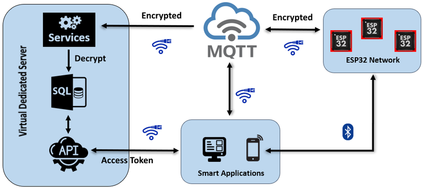
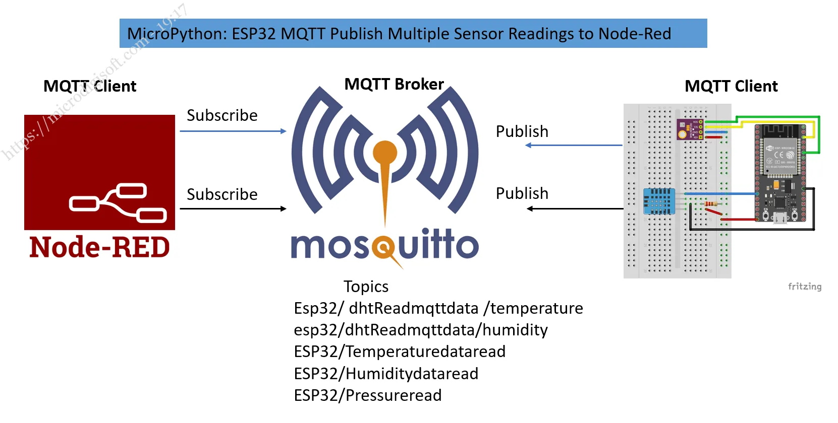
The project establishes a complete MQTT ecosystem where multiple components communicate seamlessly. At the heart of the system is the Mosquitto MQTT broker, typically installed on a Raspberry Pi, which manages all message routing between clients.
Here's how the communication flows in our specific implementation:
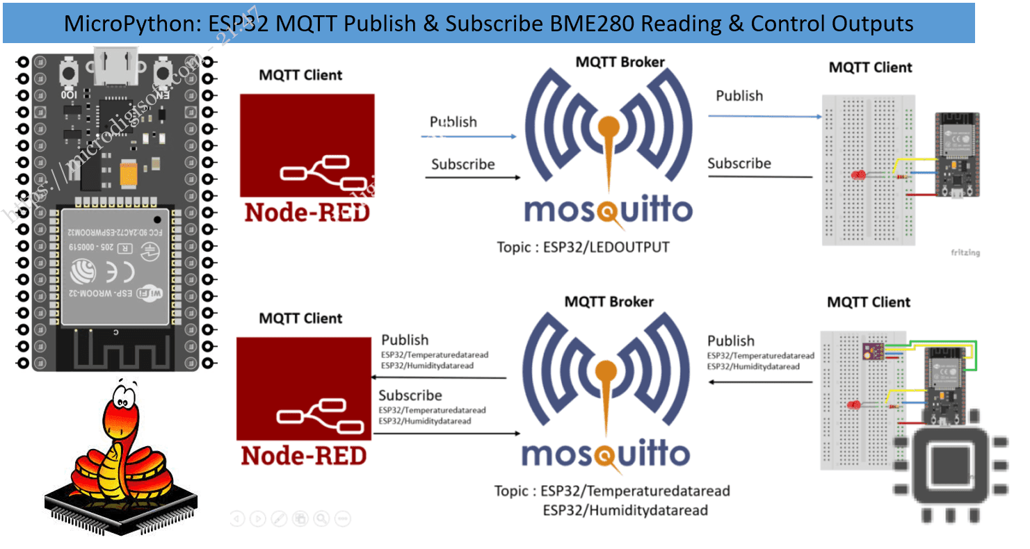
1 Control Path
The Node-RED application publishes "on" or "off" messages to the esp32/output topic. Since the ESP32 subscribes to this topic, it receives these commands and turns an LED on or off accordingly.
2 Data Path
The ESP32 reads temperature and humidity from the BME280 sensor and publishes these values to the esp32/temperature and esp32/humidity topics. The Node-RED application subscribes to these topics and displays the readings on its dashboard interface.
Prerequisites and Required Components
Before beginning this project, ensure you have the following knowledge and components:
- ESP32 development board (any variant with WiFi capability)
- BME280 sensor module for temperature, humidity, and pressure readings
- LED (any color) and appropriate current-limiting resistor (220Ω recommended)
- Breadboard and jumper wires for connections
- Raspberry Pi (any model with network connectivity) running as MQTT broker
- Micro-USB cable for programming and powering the ESP32
- Arduino IDE with ESP32 board support installed
- PubSubClient library for MQTT communication
- Adafruit BME280 library for sensor readings
- Adafruit Unified Sensor library (dependency for BME280 library)
- Node-RED installed on Raspberry Pi with dashboard nodes
- Mosquitto MQTT broker running on Raspberry Pi
- Familiarity with Raspberry Pi setup and configuration
- Raspbian OS installed on your Raspberry Pi (Lite version is sufficient)
- Node-RED installed on your Pi along with the Node-RED Dashboard nodes
- Basic understanding of MQTT concepts and operation
Circuit Assembly and Connections
Proper wiring is essential for reliable communication between components. Follow this step-by-step connection guide:
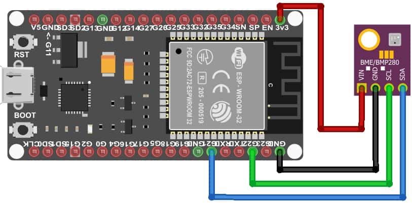
1 BME280 to ESP32 I2C Connection
- Connect the BME280 VCC pin to the ESP32 3.3V pin
- Connect the BME280 GND pin to the ESP32 GND pin
- Connect the BME280 SCL pin to the ESP32 GPIO 22 (default I2C clock pin)
- Connect the BME280 SDA pin to the ESP32 GPIO 21 (default I2C data pin)
2 LED Connection for Output Control
- Connect the LED anode (longer lead) to ESP32 GPIO 4 through a 220Ω resistor
- Connect the LED cathode (shorter lead) directly to any ESP32 GND pin
ESP32 MQTT Code Implementation
Here's the complete code for the ESP32 MQTT client with detailed explanations:
                    #include <WiFi.h>
                    #include <PubSubClient.h>
                    #include <Wire.h>
                    #include <Adafruit_BME280.h>
                    #include <Adafruit_Sensor.h>

                    // WiFi credentials
                    const char* ssid = "YOUR_WIFI_SSID";
                    const char* password = "YOUR_WIFI_PASSWORD";

                    // MQTT broker details (Raspberry Pi IP address)
                    const char* mqtt_server = "192.168.1.XXX"; // Replace with your Pi's IP

                    WiFiClient espClient;
                    PubSubClient client(espClient);

                    // Timing variables
                    long lastMsg = 0;

                    // Sensor object
                    Adafruit_BME280 bme;
                    float temperature = 0;
                    float humidity = 0;

                    // LED control pin
                    const int ledPin = 4;

                    void setup() {
                    Serial.begin(115200);

                    // Initialize BME280 sensor
                    if (!bme.begin(0x76)) {
                        Serial.println("Could not find a valid BME280 sensor, check wiring!");
                        while (1);
                    }

                    setup_wifi();
                    client.setServer(mqtt_server, 1883);
                    client.setCallback(callback);

                    pinMode(ledPin, OUTPUT);
                    }

                    void setup_wifi() {
                    delay(10);
                    Serial.println("Connecting to: " + String(ssid));

                    WiFi.begin(ssid, password);

                    while (WiFi.status() != WL_CONNECTED) {
                        delay(500);
                        Serial.print(".");
                    }

                    Serial.println("\nWiFi connected");
                    Serial.print("IP address: ");
                    Serial.println(WiFi.localIP());
                    }

                    void callback(char* topic, byte* message, unsigned int length) {
                    Serial.print("Message arrived on topic: ");
                    Serial.print(topic);
                    Serial.print(". Message: ");

                    String messageTemp;
                    for (int i = 0; i < length; i++) {
                        Serial.print((char)message[i]);
                        messageTemp += (char)message[i];
                    }
                    Serial.println();

                    // Control LED based on message
                    if (String(topic) == "esp32/output") {
                        Serial.print("Changing output to ");
                        if(messageTemp == "on") {
                        Serial.println("on");
                        digitalWrite(ledPin, HIGH);
                        }
                        else if(messageTemp == "off") {
                        Serial.println("off");
                        digitalWrite(ledPin, LOW);
                        }
                    }
                    }

                    void reconnect() {
                    while (!client.connected()) {
                        Serial.print("Attempting MQTT connection...");

                        if (client.connect("ESP32Client")) {
                        Serial.println("connected");
                        // Subscribe to control topic
                        client.subscribe("esp32/output");
                        } else {
                        Serial.print("failed, rc=");
                        Serial.print(client.state());
                        Serial.println(" retrying in 5 seconds");
                        delay(5000);
                        }
                    }
                    }

                    void loop() {
                    if (!client.connected()) {
                        reconnect();
                    }
                    client.loop();

                    long now = millis();
                    // Publish new readings every 5 seconds
                    if (now - lastMsg > 5000) {
                        lastMsg = now;

                        // Read and publish temperature
                        temperature = bme.readTemperature();
                        char tempString[8];
                        dtostrf(temperature, 1, 2, tempString);
                        client.publish("esp32/temperature", tempString);

                        // Read and publish humidity
                        humidity = bme.readHumidity();
                        char humString[8];
                        dtostrf(humidity, 1, 2, humString);
                        client.publish("esp32/humidity", humString);
                    }
                    }
- Replace all placeholder values (WiFi credentials, MQTT broker IP) with your actual network details
- For Fahrenheit temperature, replace the temperature reading line with:
temperature = 1.8 * bme.readTemperature() + 32; - The BME280 I2C address is typically
0x76or0x77- adjust inbme.begin(0x76)if needed
Node-RED Dashboard Configuration
1 Setting Up Node-RED on Raspberry Pi
Ensure these components are installed on your Raspberry Pi:
- Node-RED (standard in recent Raspbian versions)
- Node-RED Dashboard nodes for UI creation
- Mosquitto MQTT broker (
sudo apt-get install mosquitto mosquitto-clients)
2 Importing the Node-RED Flow
Instead of building from scratch, import the complete flow:
- Access the flow JSON from the project repository
- In Node-RED, go to Menu → Import → Clipboard
- Paste the flow JSON and click "Import"
- Click the Deploy button to activate the flow
3 Accessing the Dashboard Interface
Once deployed, access your Node-RED dashboard by navigating to:
http://[YOUR_PI_IP_ADDRESS]:1880/ui
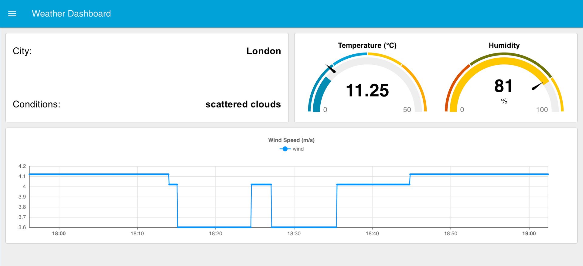
The interface displays:
- Real-time temperature chart showing historical trends
- Humidity gauge with current percentage
- Toggle switch for controlling the ESP32 LED
Troubleshooting Common Issues
No WiFi Connection
If your ESP32 fails to connect to WiFi:
- Verify SSID and password are correct
- Check if your network is available and working
- Ensure the ESP32 is within WiFi range
- Check Serial Monitor for specific error messages
MQTT Connection Failures
If the ESP32 cannot connect to the MQTT broker:
- Confirm the broker IP address is correct
- Verify the Mosquitto broker is running on Raspberry Pi
- Check network connectivity between ESP32 and Raspberry Pi
- Ensure port 1883 is not blocked by firewall
No Sensor Readings
If temperature/humidity readings aren't appearing:
- Check BME280 wiring connections
- Verify I2C address configuration (
0x76or0x77) - Ensure the BME280 library is properly installed
- Check Serial Monitor for sensor initialization errors
Advanced Applications and Modifications
This basic framework can be extended in numerous ways:
- Multiple sensors: Add additional BME280 or other I2C sensors to the same bus
- Additional outputs: Control relays, servos, or other actuators via new MQTT topics
- Data logging: Integrate with databases like InfluxDB for long-term trend analysis
- External triggers: Add physical buttons or PIR sensors to publish MQTT events
- Multiple ESP32 nodes: Create a network of devices communicating through the same broker
Conclusion and Next Steps
This tutorial has demonstrated a complete MQTT implementation with ESP32 and Node-RED, creating a functional bidirectional IoT system. The project showcases essential IoT patterns: remote sensor monitoring and device control through a lightweight messaging protocol.
- Explore ESP32 deep sleep modes combined with MQTT for battery optimization
- Implement web-based configuration portals for easy device setup
- Integrate with cloud platforms like AWS IoT or Google Cloud IoT Core
- Add local automation rules in Node-RED for conditional logic
- Experiment with different sensor types and communication protocols
The system you've built serves as a foundation for countless practical applications, from environmental monitoring stations to smart home controllers. By understanding each component's role - ESP32 as the edge device, Mosquitto as the message broker, and Node-RED as the management interface - you're equipped to design and implement increasingly sophisticated IoT solutions.